The correct operation of the hall effect camshaft position sensor (CMP) is dependent upon the integrity of the CMP circuit (power, ground and signal wiring) the fitment of the CMP in relation to the pick-up, the air gap between the CMP and pick-up, and the correct installation and orientation of the Camshaft or pick-up ring.
The camshaft or pick-up ring should also be inspected for damaged teeth and excessive run-out.
The CMP will display operational characteristics that are inconsistent due to circuit faults, electromagnetic interference, mechanical failures or measurement and connection errors.
The results obtained are therefore symptoms of underlying conditions and not as a result of a faulty CMP.
In order to efficiently perform the test, you will need the TA125 premium test lead, TA158 black battery clip and PQ070 or PP943 universal breakout lead set.
PicoScope settings
The PicoScope should be on channel A, DC coupled and the input range of ± 20 V (alternative setting of ± 10 V for CMP with 5 V output signal).
The time base should be set at 20 ms/div (alternative setting 50 ms/div for additional camshaft rotations) and sample count one MS.
Using vehicle wiring diagrams, identify the signal wire of the CMP.
The hall effect CMP will generally utilise three wires, one of which carries the signal during engine running whilst the others carry a 5V or 12V power supply and a 0V ground reference.
Connecting PicoScope
Locate and disconnect the CMP multiplug before inserting three relevant universal breakout leads between the CMP and vehicle harness in order to complete the circuit.
Then, connect the blue TA125 test lead to channel A of the scope, connect the blue test lead to the breakout lead connected to the signal wire of the CMP.
The black ground lead will then need to be connected to the vehicle chassis or battery negative terminal using the black TA158 battery clip.

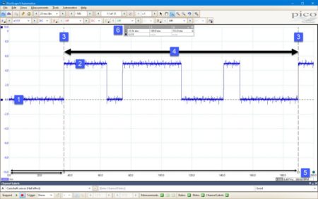
Example waveform at 20 ms/div.
When this has been completed, run your scope software by pressing either the space bar on your keyboard or the “go” button in PicoScope.
Crank and run the engine while monitoring the signal on channel A and then press the “go/stop” button in PicoScope to halt the capture and enable waveform analysis.
Diagnosis
Unlike the inductive style CMP the amplitude of the hall effect CMP signal remains fixed (regardless of engine speed), however the frequency of the signal will increase in direct proportion to engine speed.
The correct formation of the square wave signal is paramount to ensure efficient engine performance, each square pulse is generated by the movement of the camshaft pick-up passing the sensing tip of CMP.
Each pulse represents a single tooth, lug or drilling of the pick up which should therefore be uniform in structure, without deformation and identical in sequence.
Depending on manufacturer, numerous style pick-ups are utilised to denote one complete camshaft revolution.
For example, manufacturers may use one single pulse (a single lug) or multiple pulses denoting the precise camshaft position in relation to firing order, it is important to refer to the vehicle technical data.
Go to the PicoScope library for more guided tests and information by clicking ‘more details’ below.


