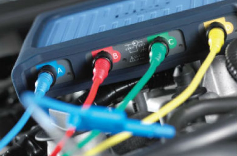
If you are new to PicoScope you may be wondering exactly how you can use it, and what benefits it will have for your workshop.
With this in mind, Pico Technology has shared a list of common uses for the PicoScope.![]()
1. Relative compression/cranking
Connect a 2000A current clamp around the positive battery cable, make sure that the orientation of the clamp is correct, with respect to the current flow away from the battery.
To capture the waveform, the timebase should be set to 200 ms per division.
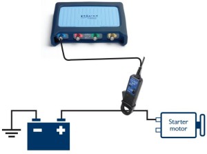 The waveform shows the amperage to crank the engine, usually between 80 and 200 amps.
Once the engine has overcome the initial friction and inertia, the waveform should settle down to a consistent ‘sawtooth’ pattern – zoom and rulers can help evaluate here, although a drop in cylinder compression is often
quite obvious.
If the waveform confirms a cylinder is losing compression, further testing with a low amp current clamp, connected to an injector or ignition coil, will help to identify the offending cylinder.
Using the WPS500X pressure transducer will highlight any mechanical issues requiring further attention.
Each peak of the sawtooth pattern should be equal and level, once settled.![]()
2. Battery, Alternator and Starting Test
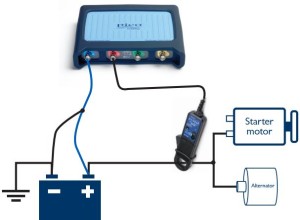 Connect a BNC cable from channel A on the PicoScope to the positive battery and a ground point on the vehicle.
Then connect the 2000 A current clamp to PicoScope and position it around the starter motor feed cable.
Follow the setup wizard in the PicoDiagnostics software to run the test.
The test result is displayed in a simple traffic light system, and covers all the starting and charging components.
This result can be printed out as a report for your customer.
This report can be customised with your workshop details and logo, as well as your customer’s information.
Remember to put the correct data in the drop-down boxes (temperature, type of battery and the battery specifications: CCA, EN, DIN).![]()
3. Diesel injector current
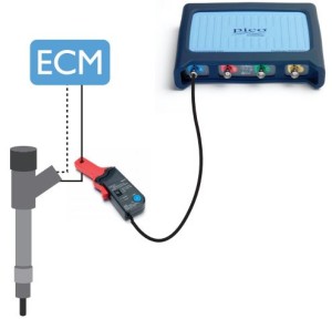 Connect using a 20 A/60 A current clamp, connect to Channel A on your PicoScope and place the clamp around the fuel injector supply wire.
You might need to connect to each wire in turn to identify the correct one.
It may also be necessary to pull back some of the loom’s outer shielding to fit the current clamp.
Run by pressing the start button or the space bar to capture the waveform (the engine must be running).
Each injection event will be visible and will include: pilot, pre-, main and post injection to confirm the fuelling strategy under all test conditions.
You can create a reference waveform to quickly compare multiple injectors on the screen.
The comparison is made easy with the rulers integrated in the software.
PicoScope software contains guided tests for all common injector makes.
Make sure that the current clamp has enough battery power.![]()
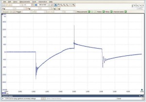 4. Ignition coil-on-plug
Locate the top of your coil packs and connect the coil-on-plug and signal probe to the PicoScope and earth to the vehicle.
The engine must be idling for this test.
Start PicoScope and place the end of the COP probe on the top of the coil pack to capture the signal.
You should see a clear signal.
The waveform will look something like the example to the right.
Now you can see every detail.
In this example you can clearly see the ‘burn time’ from the spark plug.
It also shows the coil oscillation period.
Remember how easy it is to use rulers to measure the different parts of the waveform, and our reference waveforms, to compare with different coil packs.
Move the probe around to pick up the best signal.![]()
5. Cam and crank sync
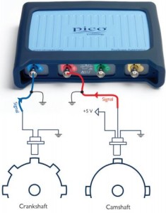 Locate sensors using the vehicle’s technical data.
Pico Technology recommends using either back-pinning probes or breakout leads to make the connection.
Use technical data to identify the signal wire.
You may need to check multiple connections to get a signal.
The engine must be idling to complete this test.
There should be a consistent pattern that develops as you capture data throughout 720° of crankshaft rotation.
With cam and crank signals, this consistent pattern can provide invaluable data for waveform comparisons.
Remember to extend the timebase to allow you to see multiple revolutions together.
If each 360° camshaft revolution is consistent, it is likely that the synchronization between the camshaft and the
crankshaft is correct, and that both sensors are working correctly.
Inconsistencies will highlight probable valve timing issues, sensor faults or short circuits.
You can find more help and advice by following the ‘more details’ link below.

