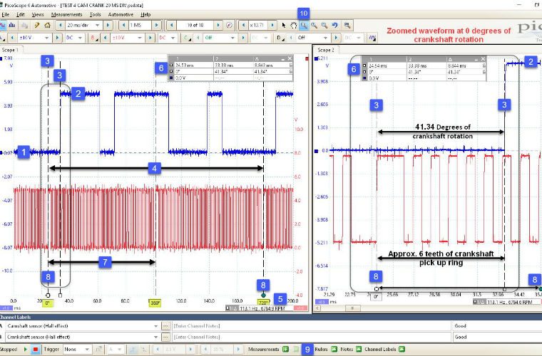
By utilizing the crankshaft signal in conjunction with the camshaft signal, technicians can non-intrusively evaluate the correlation between these critical components, while also confirming the exact style of camshaft pick-up utilized by the manufacturer.
The example waveform pictured above has a hall effect crankshaft sensor to channel B (red waveform) of PicoScope.
Based on the reference signal (missing teeth) of the crankshaft sensor signal we can clearly identify one complete revolution of the crankshaft using the rotation rulers (8) located in the bottom right-hand corner of our waveform.
Click on the rotation ruler handle (8) and drag them to positions on the crankshaft signal waveform that align with three consecutive crankshaft reference signals (missing teeth).
This will denote 0 – 720° of crankshaft rotation relative to the missing teeth of the crankshaft pick-up ring.
When you have identified 0-720°, you can introduce a single rotation ruler partition by clicking on the ruler button (9) and selecting two rotation partitions from the popup box.
The distance/time between the rotation rulers (8) will now be partitioned equally by two to indicate 360° of crankshaft rotation denoting a single crankshaft revolution (7).
Time rulers
By using the time rulers (3), you can drag one ruler to rest directly above the rotation ruler denoting 0° of crankshaft rotation (8) and the second time ruler to align with the first rising edge of our camshaft pulse after the rotation ruler denoting 0° crankshaft rotation.
The time difference between each time ruler is indicated in the ruler legend (6) along with the degrees of crankshaft rotation.
By using the zoom options (10), you can magnify the distance between each time ruler for closer analysis and accurate positioning of both the rotation and time rulers.
The right hand scope view of the example waveform highlights how the waveform will appear after zooming.
Here we can identify the 0° crankshaft reference point and the first rising edge of our camshaft pulse.
The ruler legend (6) indicates that the first rising edge of the camshaft pulse occurs approximately 41.34° after our crankshaft 0° reference point or approximately 6 teeth of our crankshaft pick-up ring (1 large tooth and 5 small teeth).
Waveform library
By using the waveform library as a reference we can now compare our captured data with an identical vehicle.
Pico’s waveform library is a cloud-based database with labelled automotive waveforms that have been uploaded by other PicoScope users from all over the world.
To access the library, you will need to have an Automotive PicoScope connected to your PC, an internet connection and a username and password for the Pico Auto forum.
Once you have obtained access to the waveform library you can search for the waveform you require using numerous search criteria such as make, model and engine code.
You can download the relevant waveform and carry out the identical measurement technique described above in order to determine a potential valve timing error attributed to timing chain or belt wear.
For vehicles with variable valve timing (VVT), it is recommended that each VVT controller is disconnected in order to restore the camshafts to their rest or full retarded position.
Refer to the VM’s technical data on how to carry out this procedure and the implications involved.
Be aware that when you disconnect the VVT controllers you will trigger and store DTCs in the PCM that you will have to delete after you have completed the diagnosis.
Click ‘more details’ below or more information, tips and advice about PicoScope.


