Nick Hibberd of Hibtech Auto-Electrical Diagnostics shares his tips and advice with Pico Automotive for users of its PicoScope.
The vehicle came in with the complaint that the ABS could be felt working through the brake pedal at very low speeds.
I carried out a short road test to verify the complaint and, sure enough, the ABS would cut in at very low speeds; in fact, just before the car came to a stop.
Apart from this the car, including the ABS system, worked as normal.
Obviously the car didn’t need any ABS intervention, so let us approach this problem with the question, ‘what is the ABS seeing where it feels it needs to intervene?’
Basics of ABS strategy
ABS monitors all four wheel speeds and, when the brake is applied, it looks to see if any wheels decrease in rotational speed at a higher rate than the others; this would indicate that a wheel is about to lock up.
The modern equivalent is now called stability control and is far more advanced than just ABS.
This vehicle is also equipped with anti-skid reduction which basically works in the opposite way to ABS; if there is any increase in individual wheel speed relative to the others (wheel slip during acceleration), then the affected wheel will receive brake pressure to reduce the slip.
During this wheel slip phase, it is normal for the engine ECU to offer torque reduction, which can come from killing the injectors, ignition retardation or other means.
However, with all this advancement, we come back to the fundamentals where individual wheel speeds are closely monitored.
We can conclude that we are dealing with the ABS strategy rather than ASR because, quite simply, the brake pedal is being applied during the fault; this eliminates ASR and gives one less aspect to worry about.
It was noted that the ABS MIL didn’t flag before, during, or after the ABS intervened, but the MIL did correctly illuminate at key-on as normal.
This is a clue that the ECU seems happy enough with its operation and that the system appears only to be acting upon information supplied to it; it sees itself as merely doing its job.
Now it’s time to hook up the scope.
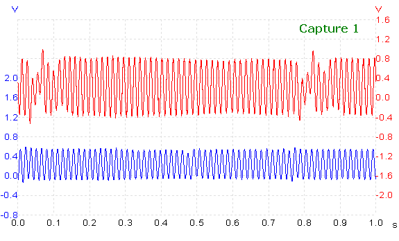
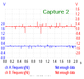
The above capture was taken at about 10 mph, with the brake pedal released and with no ABS intervention.
Channel A (blue) is monitoring RH rear WSS (wheel speed sensor) and channel B (red) monitoring LH rear WSS.
Both of these readings were recorded with the scope referenced to chassis ground — it’s important to be aware of the test conditions when looking at a suspect signal.
From this capture we can see there is a clear problem with the LH rear WSS.
To interpret the trace correctly and form a conclusion from it, we need to understand what we are looking at.
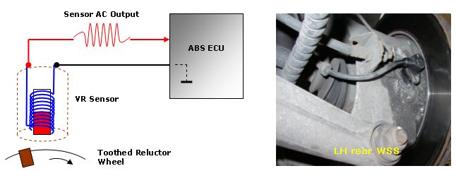
The system uses four variable-reluctance sensors, one attached to each corner hub.
Touching very briefly on sensor theory; the output of this sensor is alternating current which is generated as a moving reluctor (a metal object, in this case our wheel rotor) passes into, through, and out of the sensor’s magnetic field.
The signal signature is determined by only a few key factors that need to be highlighted:
- Sensor’s internal magnetic field strength
- Number of windings housed within the sensor
- General shape and composition of moving reluctor
- Distance between sensor and moving reluctor
- Speed at which the moving reluctor passes through the sensor’s magnetic field
Each factor plays a very important part in creating a valid signal; lose any one of these and the output signal will suffer.
As the reluctor moves into the sensor field, a positive EMF is generated, and as the reluctor moves away from the sensor field, a negative EMF is generated, usually with the same amplitude as the positive peak.
We can say that each positive peak represents one reluctor or tooth on our rotor wheel (not a strictly true analysis, but it’s good enough).
I’ll leave the theory at that, as I’m sure the reader is well aware of this sensor and its operation.
This of course is how to create a signal, but what any individual application does with this signal is an entirely different matter.
This particular system has one of the sensor cables grounded through the ECU, leaving the other cable as the main speed output signal back to the ECU.
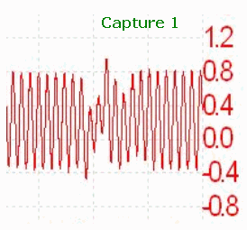
If we look at capture one closely we will see both outputs centred just above 0V, but don’t confuse this with a “floating ground” signal reading.
As mentioned, the ECU applies a ground to one of the sensor outputs, so ordinarily we would now expect to see the generated AC centred around this potential.
However, this system also fixes the sensor output line at 0.18 V (as a diagnostic aid for the ECU), so now the sensor generated AC rides along this new reference.
See capture two – all of the sensors on this system matched this signal characteristic.
Referring back to capture one, this small extract shows a poor signal being generated; so something is wrong with one of the key factors mentioned earlier.
From the mere fact that the sensor is able to generate a suitable output for the given wheel speed, we can rule out sensor magnet strength, number of windings, and speed of reluctor.
These are pretty constant factors here and it would be ridiculous to think that any one of these was absent at that one particular time.
To anyone who hasn’t seen this kind of abnormal signature before, it’s very indicative of a failed reluctor wheel.
We are left with shape and composition of reluctor and distance between reluctor and sensor.
A closer inspection of this reluctor was needed.
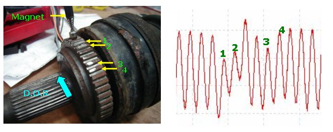
With the LH rear driveshaft removed, a possible issue was found with the rotor.
Notice the unusual shiny spots on some of the teeth. Was this the problem?
Distance between reluctor and sensor
This doesn’t seem to be an issue.
The affected teeth still had good structure compared to all the rest.
This means good height, tooth width, good general dimension, and good spacing between the teeth.
According to the capture, our problem is only in one area of the rotor, and these shiny spots correlated well with the recorded capture, but a distance problem between sensor and tooth isn’t the problem here.
Shape and composition of reluctor
The shape of the teeth has already been covered and eliminated; it was the make-up of the shiny spots that was now in question.
The sensor houses a magnet and relies on the reluctor being easily susceptible to a magnetic field.
If the material used as a reluctor is made from a weakly magnetic (non-ferromagnetic) material, the sensor’s own magnetic flux will not change easily; and no change in flux means no signal generated.
A dead simple way to test the magnetic properties of the reluctor (our teeth) is to hold a known good magnet close to the teeth and feel the force of attraction.
It’s not very scientific and seems a little crude, but it works, and judging from the scope capture we should experience a distinct difference.
Several teeth outside the suspected area on the rotor were checked like this to gain a sense of what force to expect.
When the shiny spots were checked, a low magnetic attraction was felt.
The capture shows the shiniest teeth generating the lowest EMF, as indicated one and two.
It was later discovered that the vehicle owner had had some extensive work done previously in that corner of the car, and this rotor had subsequently suffered damage and been repaired.
The repair was actually very good work from a machining point of view but, unintentionally, the repair didn’t agree with the WSS.
How is this linked to the ABS activating when approaching a stop?
First of all, remember that this capture was taken at 10 mph, which is well above our braking to a stop speed.
In hindsight, a good signal relationship would have been to view LH rear WSS against ABS pump command; this way we would have seen what signal threshold the ABS decided was enough.

The amplitude of the signal from our LH rear WSS had clearly been affected by the rotor repair, but the frequency of the signal still remained.
And if the frequency still exists, we still have a valid wheel speed signal, in a way.
Eventually, as a result of our poor reluctor, the wheel speed will drop to a level where the poor reluctor teeth can no longer generate a valid speed signal.
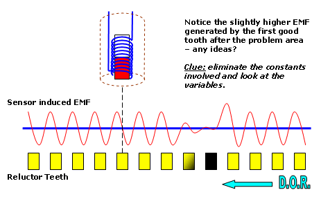
We are left with a situation where, during braking and at very slow vehicle speeds, the ABS will wrongly interpret this weak signal as wheel lock-up and so activate the ABS: our vehicle complaint.
A new reluctor wheel was installed.
Did this cure the problem? Look out for part two in the next GW news bulletin.

