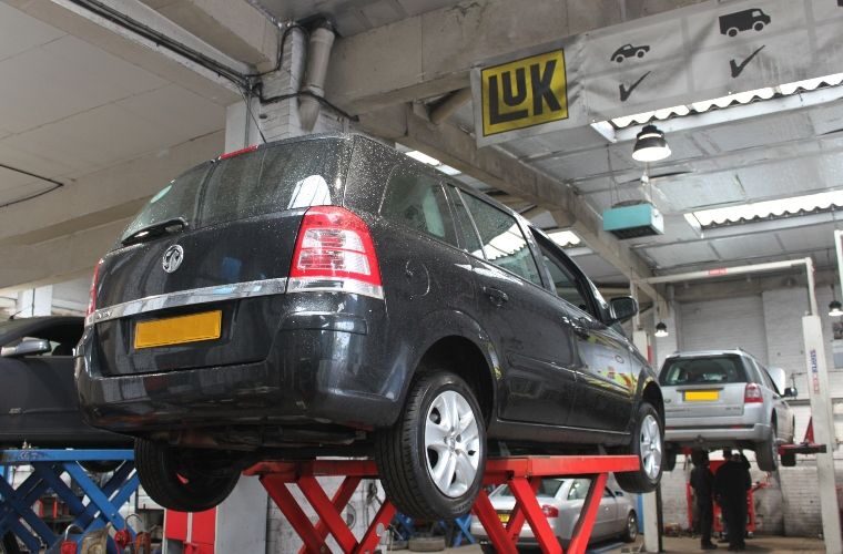
This month, REPXPERT’s Alistair Mason replaced the clutch assembly in a 2013 Vauxhall Zafira 1.7 CDTI, which had racked up more than 110,000 miles.
After complaints that the vehicle’s clutch was ‘slipping’ under full load scenarios, a short road test confirmed that a clutch replacement was necessary.
As the clutch was slipping, combined with the heat generation and miles covered, the dual mass flywheel was also replaced.
One of the main concerns when removing the gearbox from a Vauxhall is that the front sub-frame needs to be lowered or removed, but with a little insight, an independent workshop technician should be able to replace the clutch system on this type of vehicle with confidence.
With almost 430,000 Vauxhall Zafiras on UK roads, the chances of a technician working on one is high.
Equipment needed:
- Vehicle lift, two post lift is preferable
- Engine support
- Transmission jack
Prior to the repair, it is always advised to ensure you have the locking wheel bolt tool and radio code if required.
With the vehicle placed on the ramp, remove the pinch bolt from the universal joint that connects the steering column to the steering rack, located in the driver’s footwell.
Once removed, ensure the steering wheel does not rotate, as this can affect the steering angle sensor calibration.
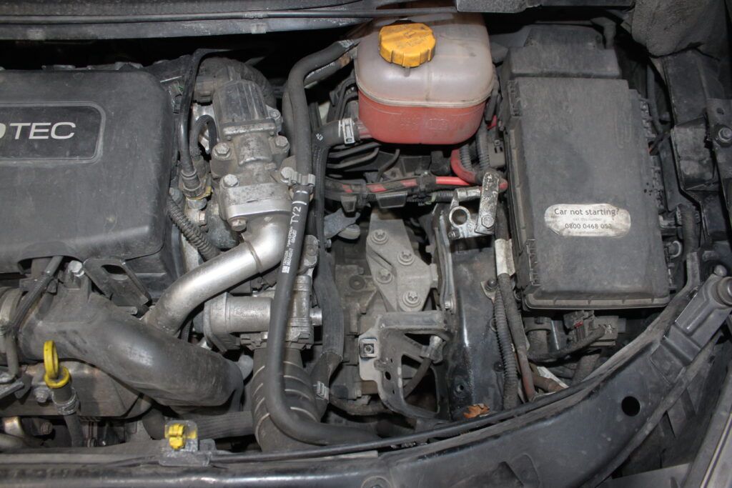
Open the bonnet, disconnect the battery, remove the battery clamp and remove the battery – then disconnect the wiring looms from the battery carrier and remove the carrier (Fig 1).
With clear access to the top of the gearbox, remove the two gear change cables from the selector mechanism and stow in the bulkhead area.
Clamp the flexible part of the hydraulic clutch pipe and disconnect the clutch pipe from the concentric slave cylinder (CSC) connection.
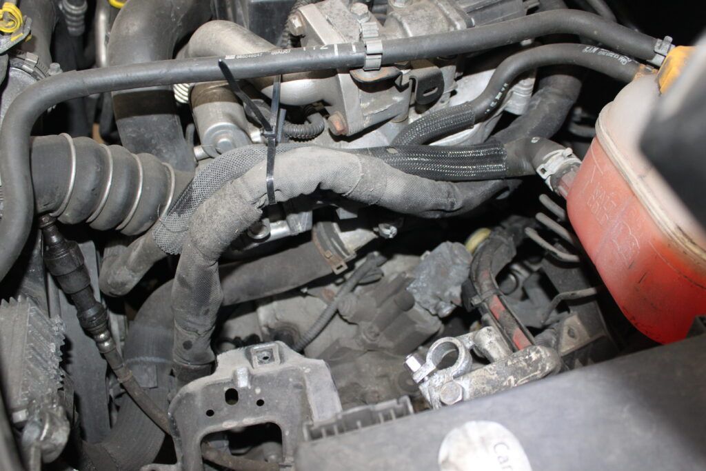
Remove the two engine wiring loom brackets from the upper bell housing – tie the looms against the engine to allow more working room (Fig 2) – disconnect the reverse light switch multiplug and then remove the upper bell housing bolts.
As the front sub-frame is going to be lowered, secure the radiator in place with two cable ties to prevent it from dropping.
Next, raise the vehicle lift to waist height and remove both front wheels. Disconnect the N/S/F anti-roll bar link, remove the N/S/F hub nut cap and then the N/S/F hub/driveshaft nut, before removing the O/S/F wheel arch splash guard.
Raise the vehicle lift to gain access to the underside of the vehicle, then remove the N/S/F bottom ball joint pinch bolt, the ball joint from the hub assembly and the rear bolts from the front sub-frame.
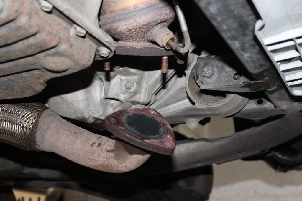
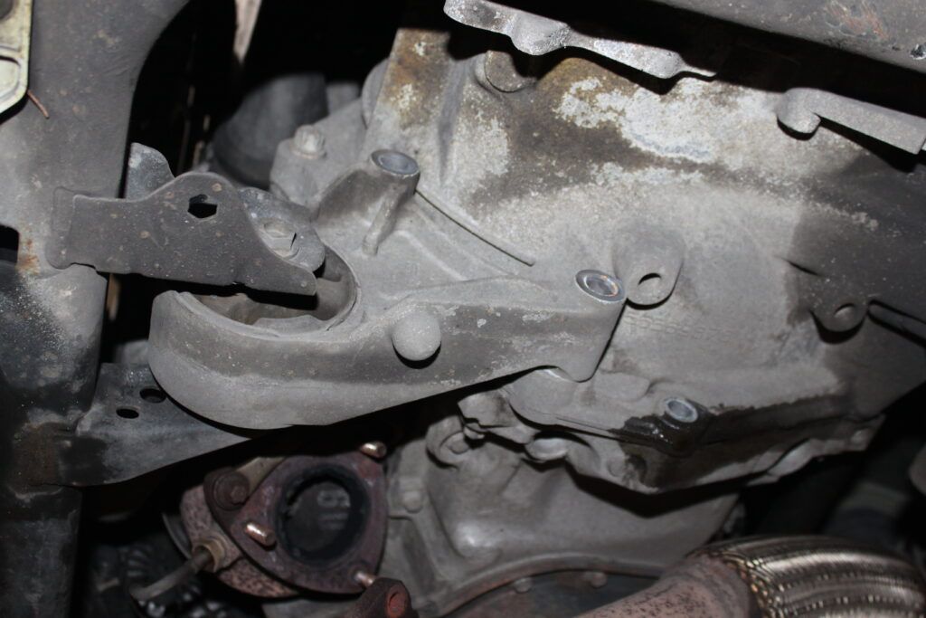
Detach the exhaust front pipe from the diesel particulate filter by removing the three nuts (Fig 3), then disconnect the rear gearbox pendulum mounting and the front gearbox mounting from the gearbox – it can stay attached to the sub-frame (Fig 4).
Support the engine by using either an engine beam on the top of the engine or a transmission jack from under the vehicle.
Unscrew the front sub-frame bolts and lower the sub-frame to give enough clearance to remove the gearbox between the vehicle body and the sub-frame.
Don’t forget to drain the gearbox oil and then remove the N/S/F driveshaft (Fig 5).
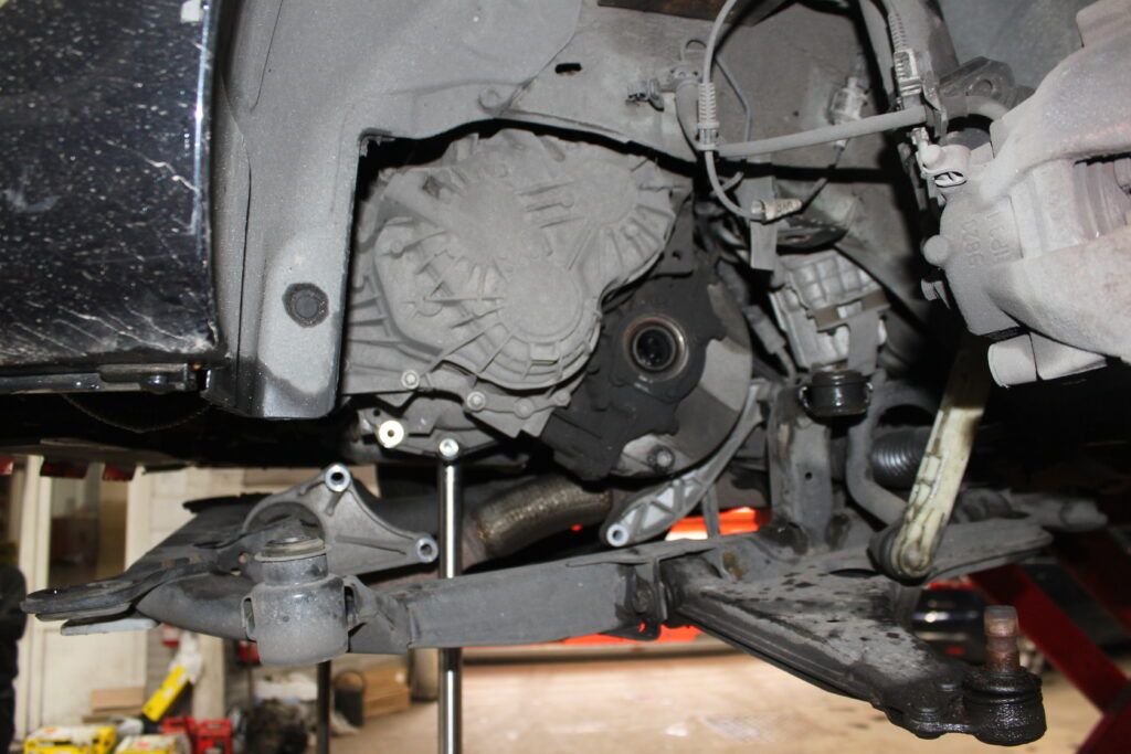
Now remove the top gearbox mounting, which may include the use of a step ladder, if supports are fitted under the vehicle.
Once the mounting has been detached, lower the engine/gearbox assembly to aid gearbox removal.
Support the gearbox using a transmission jack and remove the lower bell-housing bolts.
At this point, the gearbox is ready to be removed, which may require the assistance of a second person.
Ease the gearbox away from the engine, and, once clear, lift the gearbox over the side of the front sub-frame and then place in a safe area.
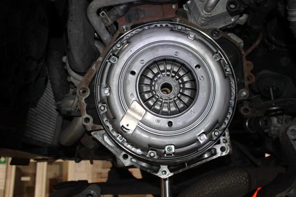
With the gearbox removed, the clutch and flywheel assembly are easily accessible.
To get a closer look at the clutch, undo the six clutch pressure-plate retaining bolts and then remove the clutch assembly.
On this occasion, the clutch was examined, and it was clear to see that the clutch plate friction material had worn to the end of its service life.
The dual mass flywheel was then removed by unscrewing the eight fixing bolts.
At this point, examine the back of the engine for any oil or coolant leaks that could contaminate the new clutch and flywheel assembly, rectifying if necessary.
Clean the back of the engine with brake and clutch dust cleaner, then mount the new dual mass flywheel.
Ensure all alignment dowels locate correctly, fit the new flywheel bolts, tighten and torque to the manufacturer’s specification.
Replacing the CSC
The CSC must always be replaced when replacing the clutch assembly to ensure a complete repair.
Remove the pipe guide that passes through the bell-housing, then, once that task is complete, unbolt the three CSC retaining bolts and then the CSC.
Clean the bell-housing area, ensuring all the old clutch dust has been cleared, and carefully mount the new CSC, of which the gearbox input shaft oil seal is an integral part.
Guide the pipe through the bell housing, then, once neatly in position, fit the three retaining bolts and torque to the recommended specification. Finally, refit the pipe guide back into the bell-housing.
Lightly smear some high-melting point grease onto the splines of the gearbox input shaft, before mounting the new clutch plate onto it, moving back and forth, as this will confirm the clutch plate fits correctly and will evenly distribute the grease. Remove the clutch plate and wipe off any excess grease.
When mounting the clutch assembly, ensure the clutch plate is facing the correct direction – this is indicated by either ‘Gearbox Side’ or ‘Getriebe Seite’ stamped onto the centre of the clutch plate – by using a clutch alignment tool.
With the clutch plate mounted correctly, lift the clutch pressure plate, insert the six bolts, tighten evenly and sequentially and torque to the recommended value.
The clutch assembly fitted to this vehicle is a ‘Travel Adjusting, Self-Adjusting Clutch’, which can be recognised by the adjuster mechanism (Fig 6).
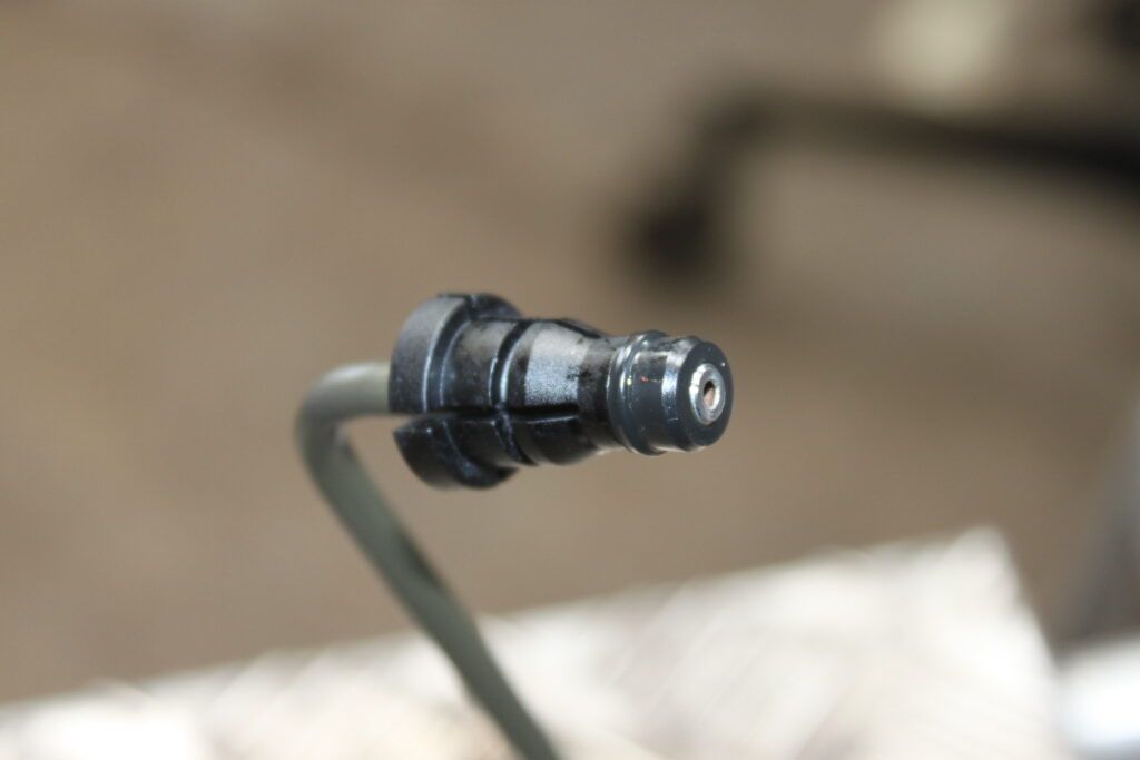
A critical part of this repair is to locate and remove the small rubber ‘top hat’ seal from the end of the CSC pipe (Fig 7).
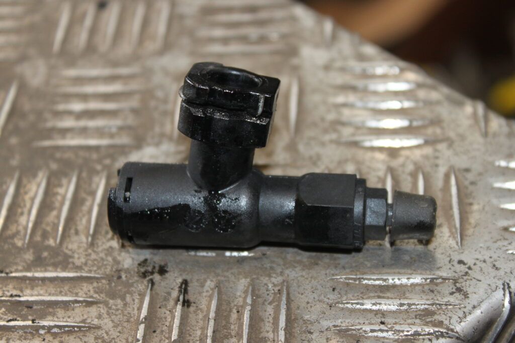
It will either be attached to the CSC pipe or in the connector that attaches to the pipe (Fig 8) and must be located and discarded, as the new pipe has a new seal pre-fitted.
The last task to carry out before refitting the gearbox is to flush out the old clutch fluid and replenish the system with new fluid, achieved by placing a drain-tray under the hydraulic pipe, releasing the clamp and allowing the fluid to run through.
The reservoir can be topped up as required, until the new fluid is running through, before re-clamping the pipe.
The gearbox is now ready to be installed.
To ensure the gearbox alignment dowels are located correctly in the engine, a second person may be required.
Ease the gearbox into position and locate on the dowels; once located, fit a bell housing bolt, which is easily accessible, and tighten to secure in position.
Installation is carried out in reverse order of removal.
When the gearbox is located on its mountings, bleed the clutch to confirm correct operation and remember to refill the gearbox with the correct quality and quantity of gearbox oil.
Always remember to reset electrical systems after the battery has been reconnected and carry out a good road test to ensure a quality repair.
Information on Schaeffler products, fitting instructions, repair times and much more can be found on the REPXPERT garage portal, or calling the Schaeffler technical hotline on 01432 264264.




Home Page › Forums › Guide: Vauxhall Zafira clutch replacement