On cars fitted with a hydraulic clutch actuation system, low-frequency vibrations generated by the engine firing impulse and crankshaft imbalance are transmitted by the clutch cover through clutch bearing and hydraulic column to the clutch pedal as hydraulic pulsations.
This kind of pulsations can be felt by the driver when he depresses the clutch pedal, which is typical for urban traffic, or when the driver is waiting at the traffic light and is holding his foot on the clutch pedal.
Three technical solutions are mainly used to cancel or to reduce this kind of pulsations; damping or reducing pulsation amplitudes, modulating the pulsation frequency and isolating the hydraulic circuit up to the clutch master cylinder.
Dampers
Hydraulic pulsations are sensitive to volume variation, so a higher volume of the hydraulic system means a higher pulsation damping.
To achieve this, several solutions are used.
These may include rubber hoses with elastic walls, increasing the length of metal pipes, having ”S”, ”U” or spiral shape, different pipe cross-sections added on the same fluid connection, adding elastic elements in the system and elastic elements integrated in a pressure chamber.
Although these solutions are effective in reducing or cancelling hydraulic pulsations, they have a few drawbacks, because of the increase in volume, frequency and temperature dependency.
Damping by increasing the volume of the hydraulic circuit may be felt by the driver as elastic pedal (softness) and lack of tactile feedback, having a longer stroke.
If the volume increase occurs mainly at the beginning of the clutch pedal stroke, when the pressure in the system is low, the pedal stroke and the pressure will increase too.
However, the volume will remain more or less the same and therefore, pulsation cannot be reduced in this situation.
Having longer pipes with higher flow resistance leads to apply a greater force when operating the pedal and reduces the return speed of the pedal, especially as the temperature decreases (the brake liquid becomes thicker).
Many systems are frequency-dependent, not being able to reduce pulsation on the entire frequency range.
As an OE, OEM and OES supplier for automotive brake and clutch hydraulic systems, FTE Automotive develops solutions to ensure a maximum driving comfort, cost efficiency and space reduction.
Today, FTE solutions are oriented less towards damping pulsations from the clutch hydraulic system and more towards modulating the vibration frequency or isolating vibrations.
The slave cylinder together with the clutch actuation system are integrated as a vibration source or the transmitter, whereas the clutch master cylinder and clutch pedal make up the oscillating system or the receiver.
Both systems are connected to each other by the pressure line or by a quasi-stationary hydraulic system.
Frequency modulators
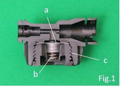
Engine vibrations are transmitted in the system as low-frequency pressure pulsations by the pressure line up to the frequency modulator, whose membrane will vibrate at a much higher frequency than that of the disruptive source.
The high-frequency pulsations are transmitted to the master cylinder – clutch pedal assembly.
Because of the inertia, the assembly will have no response and the driver will feel nothing.
The frequency modulator means there is no there is no temperature dependence.
It also results in a more sensitive response to pressure variation in the system.
The housing produced through plastic injection molding is cheap and requires no other processing steps.
The housing and the closing cap have a rounded thread profile, which guarantees the durability of the housing.
It enables technicians to bleed the system so that no residual air remains afterwards.
The possibility of increasing the diameter/thickness ratio of the metallic membrane has a great impact on hysteresis loss and on system elasticity, which should be as small as possible.
The usage of the pretensioning coil spring allows controlling volume development.
Because the metallic membrane is pretensioned by the coil spring, volume expansion is reduced, leading to a stiffer pedal, a shorter stroke as compared to systems not having this pretensioning coil.
Frequency modulators can be set up for almost any kind of system, using the same housing, just by adapting the thickness and the diameter of the metallic membrane and the rigidity of the coil spring.
Isolators
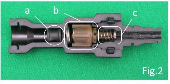
The pulsation isolator is installed on the hydraulic line, between the master and slave cylinders.
Inside of housing two valves are fitted by two coil springs.
Each valve can be opened only when the hydraulic fluid is flowing depending on the direction of the flow.
For example, the b valve from Fig. 2 opens when the master cylinder is actuated and the fluid flows from the master cylinder to the slave cylinder, whereas the c valve closes.
If the clutch pedal is released, the fluid will flow in the opposite direction and the c valve will open and the b valve will close.
The valves only open when the fluid flows through the system and they close when there is no fluid flow.
If the clutch pedal is depressed and the hydraulic system is under pressure (there is no fluid flow in this stage), the valve system can actually separate (isolate) the fluid columns between the isolation device and master cylinder and between the isolation device and slave cylinder.


