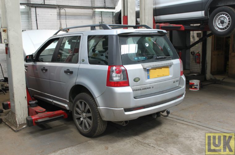
Schaeffler LUK has released a clutch feature on a 2008 Land Rover Freelander 2 TD4 featuring a clutch replacement demonstration that illustrates why this is a straight forward repair for any garage.
Fitted with a 2.2 TDI engine, the vehicle has covered just over 133,000 miles and has been brought into the workshop with reported clutch slip; a short road test confirmed this, and clutch replacement was advised.
On an initial inspection, this can look quite a large job with a book time of five hours, but with some guidance from REPXPERT Alistair Mason this is a straight forward repair for any independent workshop, Schaeffler asserted.
Prior to starting the repair, it is recommended technicians have the vehicle’s locking wheel nut key, and it is always advisable to check Schaeffler’s REPXPERT workshop information portal for any technical bulletins, should advice be updated.
For this repair, the workshop equipment required is:
– Vehicle lift (two post is ideal)
– Transmission jack
– Engine support
– Gearbox oil dispenser
Step One
–
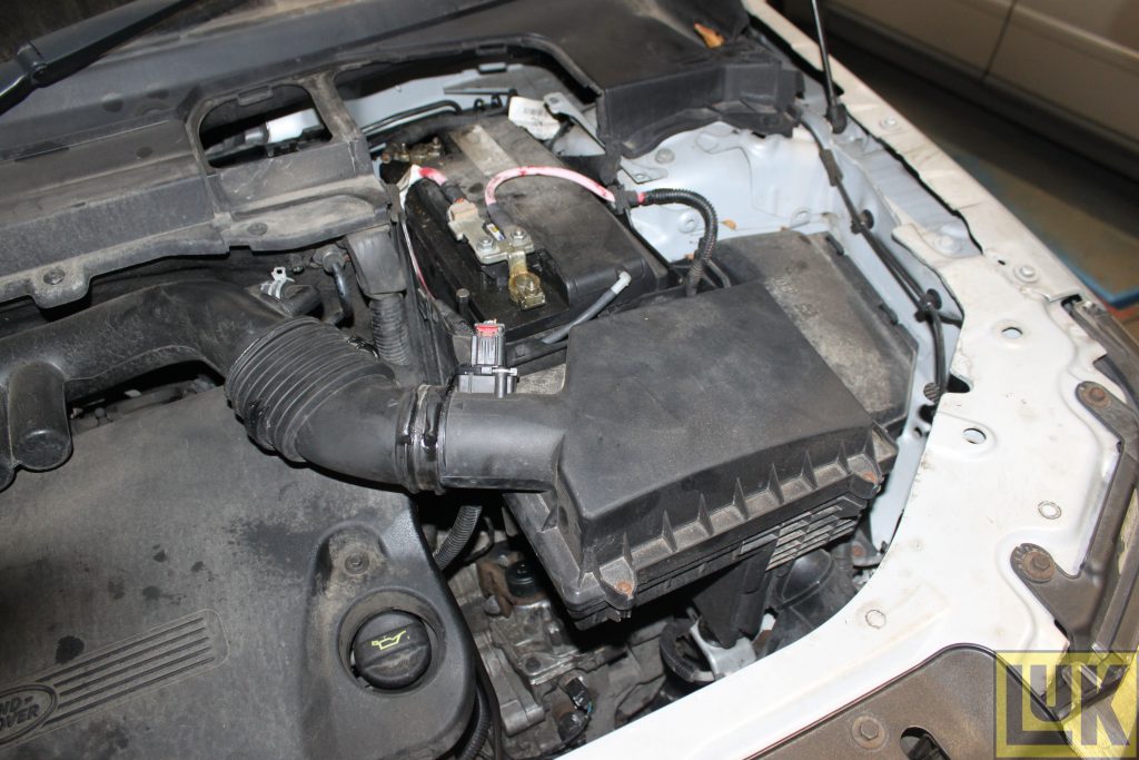
With the vehicle positioned on the vehicle lift, open the bonnet, remove the battery, battery carrier and air filter assembly – this improves access to the top of gearbox
Step two
– Disconnect the gear cables, clamp the flexible part of the hydraulic clutch pipe and then disconnect the clutch pipe from the concentric slave cylinder connection
– Disconnect the electrical multiplugs from the front of the gearbox and stow in a safe area
– With the vehicle still on the ground, slacken the O/S/F hub nut – as the driveshaft has to be removed later in the process – and slacken both front locking wheelnuts
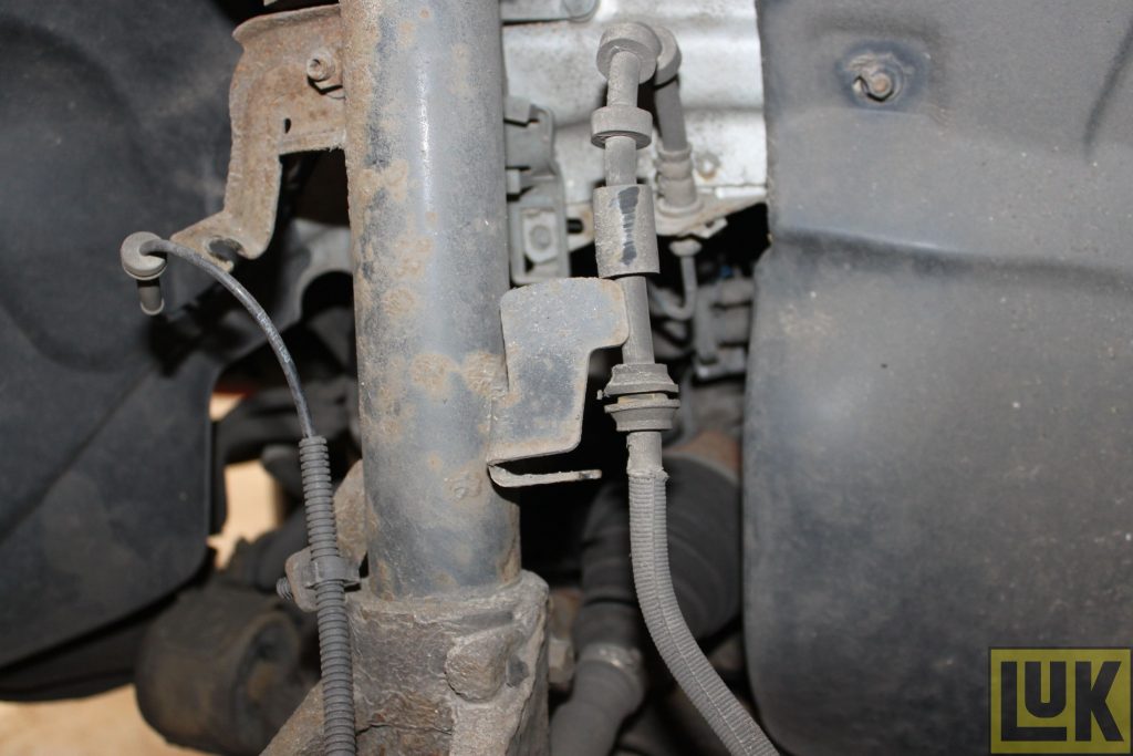
– Raise the vehicle lift to waist height, remove both front wheels, release
both front flexible brake pipes and ABS wiring looms from the retaining brackets and remove both inner wing panels to expose the gearbox and the engine (below)
Step three
– Raise the vehicle lift to gain access to the underside of the vehicle
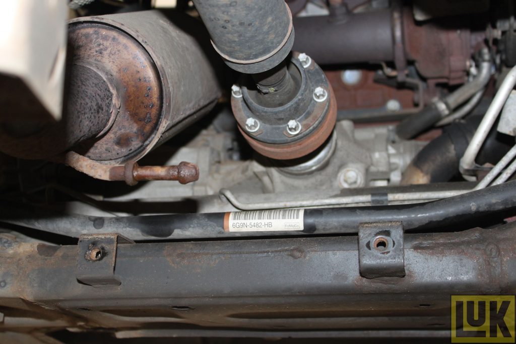
and remove the engine undertray– Technicians now need to remove the front sub-frame assembly (below)
– Firstly, secure the steering rack in position by strapping it to the front struts, disconnect both front ball joints from the hub carriers, remove the exhaust mounting located at the rear of the subframe, and then remove the mounting bolts for the antiroll bar and steering rack
– Support the sub-frame using a transmission jack, remove the four subframe retaining bolts and lower the sub-frame on the transmission jack and stow in a safe area (a second person may be required to assist in the sub-frame removal)
Step four
– Drain the gearbox oil and transfer box oil
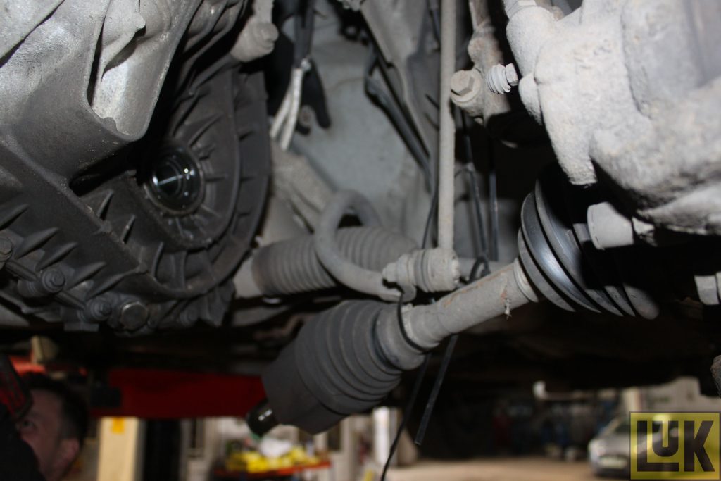
– Whilst the oil is draining, remove the turbo intake pipe that runs under the engine and then remove both front driveshafts from the gearbox – the N/S/F driveshaft can stay attached to the hub assembly and be secured to give clearance (below)
Step five
– The O/S/F driveshaft needs to be removed from the vehicle; at this point refit the drain plugs and torque to the manufacturer’s specification (below)
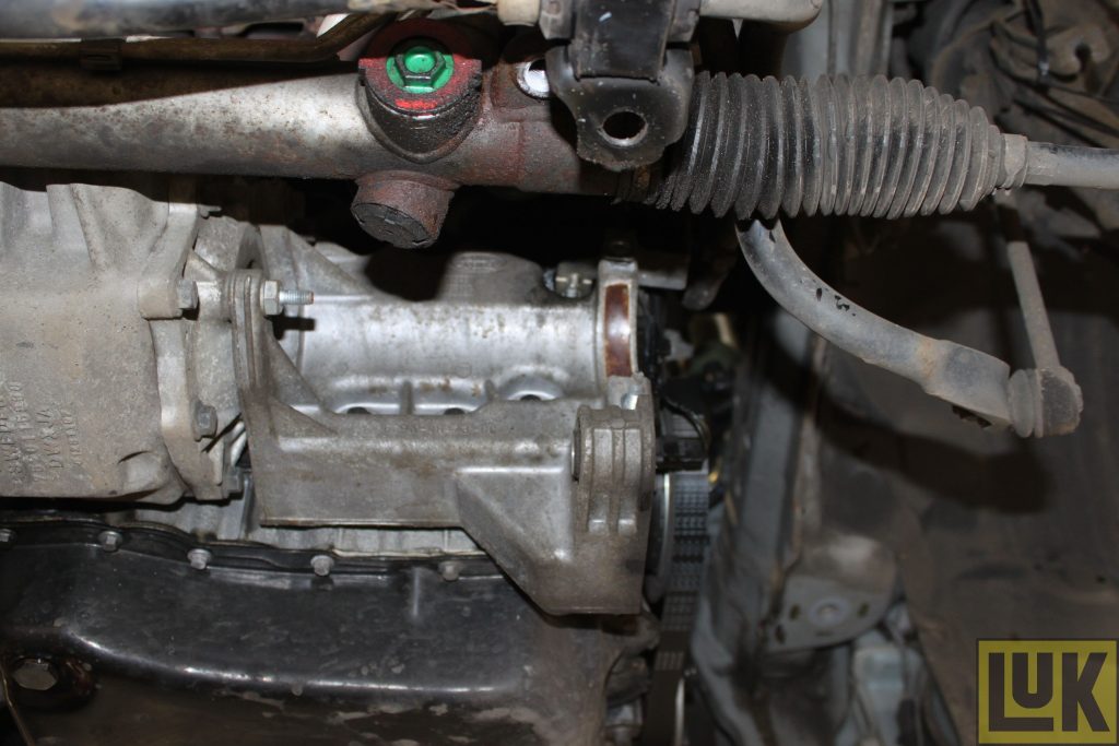
– With the O/S/F driveshaft removed, remove the centre bearing carrier bracket from the transfer box and engine, before disconnecting the prop shaft flange from the transfer box (note, it is always advisable to mark the flange location position prior to removal to avoid any balance related issues after the repair)
Step six
– Remove the breather pipe from the vent on the top of the transfer box
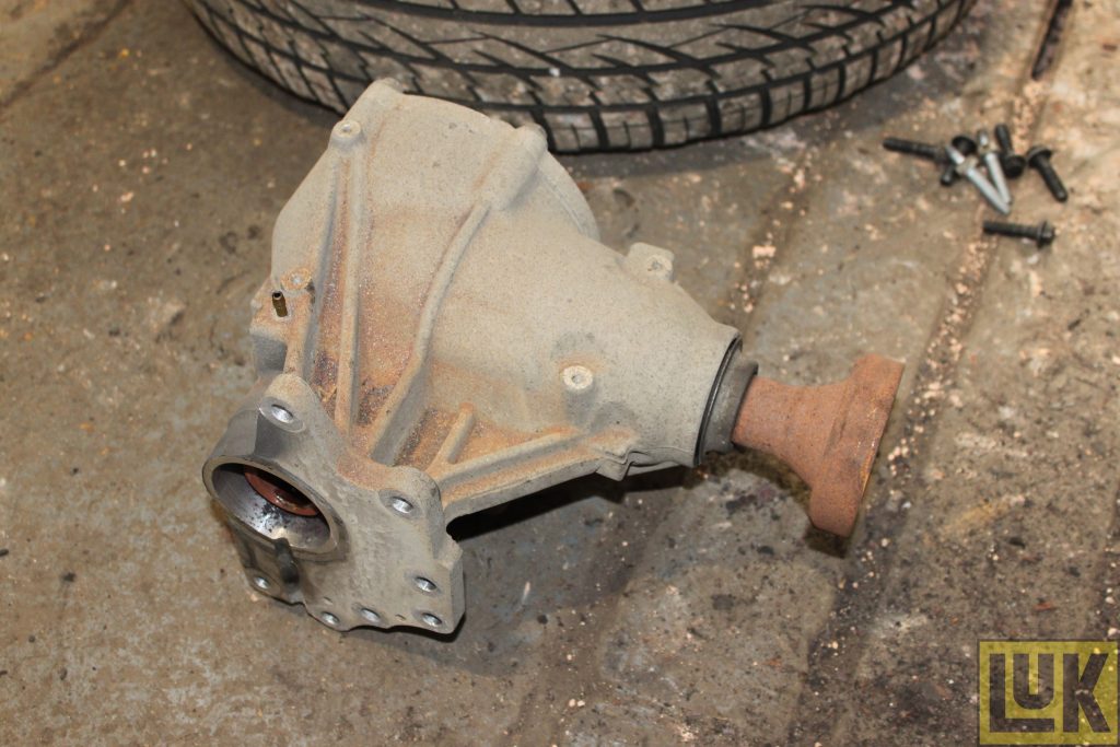
– Remove the seven retaining bolts and remove the transfer
box from the gearbox and stow in a safe area (below)
Step seven
– Remove the bell housing bolts – leaving in an easily accessible place
– Bolt to retain the gearbox in position; support the engine using either an engine beam or a second transmission jack
– Remove the upper gearbox mounting and then lower engine slightly to aid gearbox removal
– Remove the earth strap connected to the gearbox mounting bolt and
then remove the mounting assembly
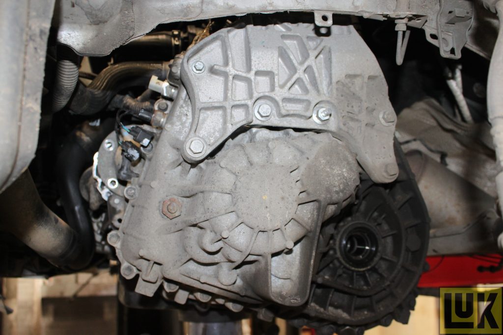
Step eight
– Support the gearbox with the transmission jack, remove the final bell housing bolt and then ease the gearbox away from the engine
– Once clear of the clutch assembly, lower the transmission jack and remove the gearbox; place in a safe area.
– With the gearbox removed, remove the clutch assembly from the flywheel
Upon examination from Schaeffler’s REPXPERT, it was clear to see that the clutch plate had reached the end of its service life as it had worn close to the friction material rivets.
The dual-mass flywheel was replaced upon the customer’s request and,
in this instance, excess heat was evident by the “blueing” on the flywheel face.
– Remove the dual mass flywheel and check for any leaks on the back of the engine; rectify as required so not to contaminate the new clutch components
– Clean the back of the engine with brake and clutch dust cleaner,
ensure the new flywheel locates correctly, secure into position with the new flywheel bolts and torque to manufacturer specification– Clean the bell housing area with brake and clutch dust cleaner, unclip and withdraw the concentric slave cylinder adaptor/extension pipe and then remove the concentric slave cylinder (CSC)
– Ensure the CSC mounting surface is clean and install the new CSC, torque the retaining bolt and then fit the new adaptor/extension pipe
– Smear a small amount of high melting point grease on the input shaft
splines and then slide the new clutch plate onto the input shaft – this will ensure the clutch plate has the correct splines– Evenly distribute the grease, remove the clutch plate and remove any
excess grease– Mount the new clutch assembly onto the flywheel using a clutch alignment tool
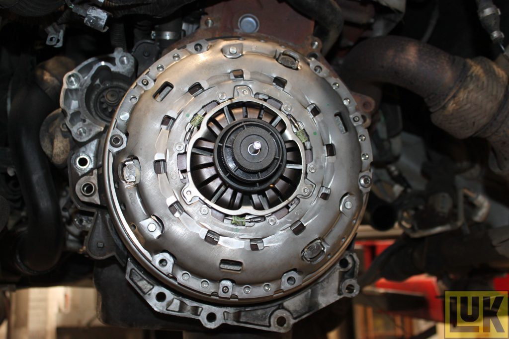
– Ensure the clutch plate is fitted correctly, with “Gearbox Side” or “Getriebe Seite” facing the gearbox and that all the clutch faces are clean
– When installing the clutch bolts, tighten and torque in an even and sequential manner
– It is always best practice to flush/change the clutch hydraulic fluid when replacing the CSC; this is done quite simply by removing the clamp from the hydraulic clutch pipe and flushing the fluid through into a drainer until the clean fluid is running through
– Once flushed, clamp the hydraulic pipe ready for the gearbox installation
– Finally, ensure the engine to gearbox alignment dowels are installed in the engine before installing the gearbox
– Place the gearbox on the transmission jack and ease into position – it is always worth speeding a little time to ensure the gearbox is at the correct height and angle on the jack to aid installation
– When the gearbox is located correctly, secure with an easily accessible bell housing bolt and installation is in reverse order of removal
Remember to refill the gearbox and transfer box with the correct
quality and quantity of oil and to reset electrical systems and control units when the battery lead has been reconnected; a final road test will ensure a quality repair, Schaeffler said.
Schaeffler is a global supplier of parts to the automotive aftermarket, featuring OE-quality products.
Information on their range, fitting instructions and repair times can be found by clicking ‘more details’ below.

