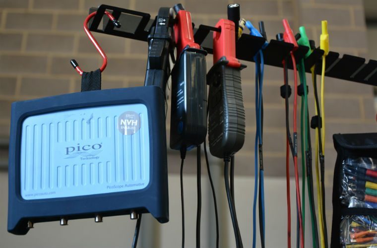
Pico Technology, the automotive PC oscilloscope and data logging brand, has released a guide explaining how technicians can quickly test and identify injector current changes between idle, acceleration and overrun conditions.
A Connection for diagnostic work will vary dependent on application, Pico Technology has said.
Technicians should, whenever possible, gain access to the test circuit without damage to seals and insulation.
If this is not possible, they should make sure appropriate repairs are completed before any test begins.
Advice before connection test
PicoScope offers a range of options within the test kits.
Dependent on the difficulty of access, technicians can choose from breakout leads or back-pinning probes.
Testing sensors and actuators
When testing a sensor, Pico Technology has said it is desirable to gain access at the control module.
With the actuator, it is desirable to gain access at the actuator.
Preparation before working on vehicle
The test involves working with a system having potentially hazardous voltage, therefore technicians are urged to follow manufacturer safety instructions and working practices.
The rated voltage for all accessories workshops are using should meet or exceed the expected voltage.
Do not electrically disconnect a piezoelectric injector with the engine running.
Ensure secure diagnostic electrical connections are made.
How to perform the test
1. Connect the low amp current clamp into PicoScope Channel A.
Set the clamp to the 20 A scale and zero the clamp before connecting to the injector supply circuit.
2. Start the engine and allow it to idle.
3. Minimize the help page and with the example waveform on your screen PicoScope has already selected suitable scales for you to capture your waveform.
4. Start the scope to see live data.
5. Vary the accelerator pedal to see idle, acceleration and overrun injector waveforms.
6. With your waveforms on screen stop the scope.
7. Turn off the engine.
8. Use the Waveform Buffer, Zoom and Measurements tools to examine your waveform.
Check for live waveform
The orientation of the current clamp relative to the wire will determine whether it has a positive or negative output.
If a live waveform does not appear on your screen or appears to be inverted, try reversing the orientation of the clamp.
Waveforms to look out for
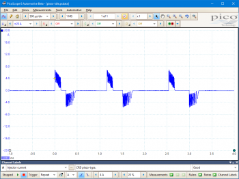
Engine at Idle:
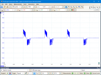
Increased torque demand:
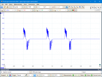
High engine speed:
Overrun:
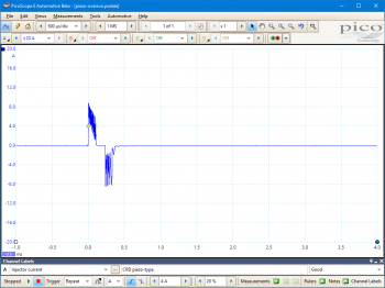
Characteristics of good waveforms
One or more pairs of positive and negative pulses, which respectively drive the opening and closing of the injector is an indicator of a fully operational system.
The pulses have peak amplitudes around ±7 A and cycle from 0 A to their peak value and back within 100 to 200 µs (the precise values will vary with system and test conditions).
For more about Pico Technology and the piezo injector current test for diesels as well as petrol vehicles, click ‘more details’ below.

