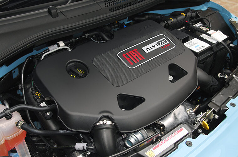
In this case study, Pico Technnology’s Steve Smith outlines the diagnostic techniques involved when faced with a misfire symptom during cold starts in engines that utilise TwinAir technology.
Customer’s description
The customer reported a severe vibration from the engine when starting from cold. The vibration was accompanied by a fuel smell from the exhaust and an engine warning light (MIL).
Technical description
Verifying the customer’s complaint is an essential step in the diagnostic process but it is also quite often a time-consuming task without success. On this occasion, the customer’s complaint performed right on cue and we quickly identified that the engine was misfiring from cold. Explaining the vibration, fuel smell and illuminated MIL.
Free revving, the engine would allow the engine to run smoothly and on return to idle the misfire had improved. At this stage, it is worth mentioning that the vehicle in question was a two-cylinder design, and so losing one cylinder had a detrimental effect on engine vibration and performance levels.
The video below uses NVH to capture the misfire condition during cold start, where we obtained a clear E0.5 engine vibration order during the initial start-up.
Note that a two-cylinder engine has one combustion event every revolution of the crankshaft, therefore, a misfire introduces one disturbance every two revolutions of the crankshaft (one disturbance/two crankshaft revolutions = E0.5).
For more information on misfire detection with PicoDiagnostics NVH, check out this forum post.
Diagnosis
With the customer’s complaint verified, we confirmed the vehicle’s ID and specification. Confirmation of vehicle specification is vitally important when it comes to diagnosis, as there is often a temptation for customers to modify their car with fashionable accessories that lack the fundamental quality control and engineering that was intended for the vehicle. The customer confirmed that no such accessories had been installed.
To establish facts from fiction, the customer interview follows the four ‘targeted’ open question principle below:
- How long has the problem been evident? Periodically for three months.
- When did you first notice the problem? During the winter months (cold weather).
- Has any work been carried out on the vehicle recently? The engine oil and filter had just been replaced due to a low oil level warning light appearing on the instrument panel. (This was not verified.)
Further quizzing of the customer revealed the previous oil change was carried out three years ago given they only drive around 3,000 miles per year.
- When do you experience the problem? When the vehicle has been left standing for long periods and only when the engine is started from cold.
The basic Inspection confirmed no fluid leakages, no visible signs of damage to hoses, connections, wiring harnesses or accident repair.
A vehicle scan of all on-board control units revealed several fault codes, as listed below:
IAW 8GSF CAN
P0301 Misfire detection, cylinder one: Temperature too high
P0300 Misfire detection: Temperature too high
P1061 Inlet solenoid valve lift Valve control Cylinder 1: Component sticking
Audio/telematics 4.0.2: U0019 CAN data bus B CAN bus off
Central electronics CE 4.1: B10AA Configuration Internal fault
To summarise the vehicle scan: cylinder one misfire codes appear to be the order of the day.
Before we dive in, it is important to take a step back and check for TSB (recalls and Campaigns etc.). There are numerous ‘known faults’ listed for the operation of the variable valve lift control system (the TwinAir actuator), which predominately focus on the hydraulic functionality.
These include:
- Incorrect engine oil viscosity
- Engine oil contamination
- In-line oil filtration restriction
- TwinAir actuator rattling noise (when hot with sporadic idling)
It’s not often you obtain fault codes, symptoms and ‘known faults’ that all point to a single component. Of course, it would be tempting to replace the TwinAir actuator along with the engine oil/filter and hope for the best, but why do that when we have the means to prove all of the above before we start replacing parts?
Replacing a TwinAir actuator assembly means committing to an expensive component (at least £750) that may or may not be faulty, Remember, we have a misfire from cold, that could also be an ignition coil or spark plug failure.
Possible causes
- Ignition system
- Fuel system
- Engine lubrication system
- Engine mechanical control system
The action plan was predominately governed by accessibility, probability and cost. Based on the acquired scan data we had two engine fault codes that referred to a misfire and one fault code that referred to a component that could generate a misfire (TwinAir actuator: component sticking).
The action plan, therefore, focused on engine management:
- To take measurement of multiple sensors and actuators during the initial cold-start phase by using an eight-channel scope. This would allow us to eliminate a number of components with a single capture.
Note: After the initial 10 seconds of the engine running from cold the fault would clear and the vehicle had to fully cool again. This is where eight channels can speed up the diagnostic process, given the nature of such a symptom.
To recap
- Engine vibration from cold start
- Engine misfires from cold (improves when warm or above idle speed)
- Engine management light illuminated
- Engine rattle evident during cold start (improves when warm)
On the screenshot below, we have the initial cold start of our Fiat 500 as we monitor the following signals:
- Ch A: Crankshaft sensor (to obtain engine acceleration via math)
- Ch B: Exhaust gas pulsations (to capture post-combustion pulses)
- Ch C: Inlet manifold pressure (using a WPS500 pressure transducer)
- Ch D: Cylinder one inlet valve actuator
- Ch E: Cylinder two inlet valve actuator
- Ch F: Ignition coil cylinder one primary current
- Ch G: MAF sensor
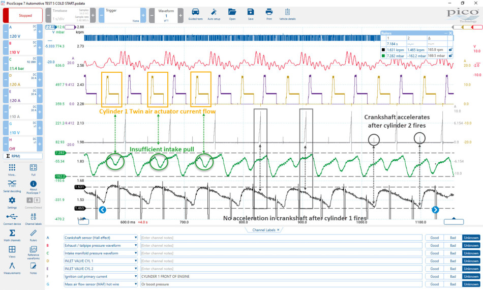
We could immediately see a number of areas of concern and eliminate several other variables.
Let me start with our crankshaft math channel: There was no doubt that our crankshaft was not accelerating after the ignition event of cylinder one, however, the crankshaft did accelerate after the ignition event of cylinder two. (We had confirmed our misfire.)
We could see from channel C that our intake pull for cylinder one (sensed within the intake manifold) was insufficient by comparison to the pull for cylinder two.
Channels D and F revealed current flow via the inlet valve actuator and ignition primary circuit for cylinder one respectively.
The screenshot below illustrates how this engine would eventually run normally on both cylinders once it was warm.
Note: Channel G has been changed to measure the primary current on the ignition coil on cylinder two.
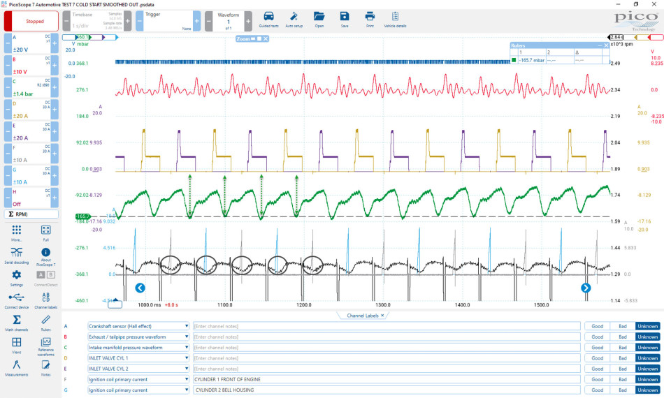
So, let’s evaluate what we had confirmed and how we were to proceed:
- Cylinder one was misfiring from cold as suggested by our fault codes.
- Cylinder one was not pulling sufficient air from the intake manifold and, therefore, the result could only be incomplete combustion.
- The cylinder one inlet valve actuator was pulling current, which suggested the status ‘work done’.
- The cylinder one ignition coil primary current suggested that our primary ignition was intact. This did not, however, confirm that our secondary ignition was present and correct within the combustion chamber.
Based on the evaluation above, I made an assumption that measuring the secondary ignition would not reveal anything about the reduced intake pull for cylinder one (our prime suspect), so adding a pressure transducer to cylinder one during cold start seemed to be the best course of action.
The results were exactly what I was hoping to capture:
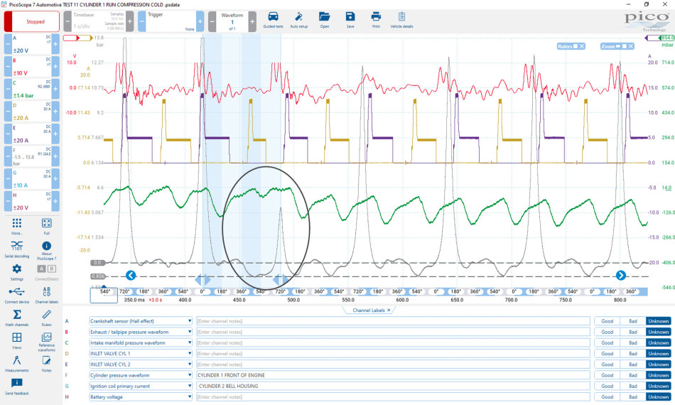
The momentary failure of the inlet valve to fully open resulted in low compression, a reduced intake pull (within the intake manifold) and of course, low combustion.
A closer examination of the four-stroke cycle during the fault condition revealed the dramatic effect the reduced air intake (intake pull) during the short inlet valve duration had on the peak compression. Note the increased depth and prolonged intake pocket associated with a restricted intake.
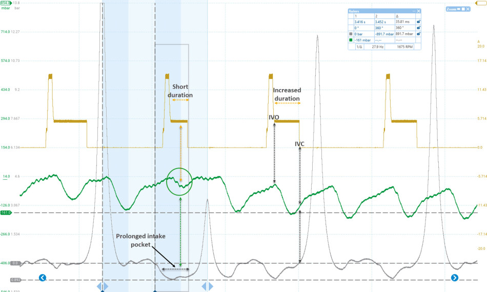
The inlet valve duration below was immediately increased on the following intake stroke in an attempt to stabilise the compression. The effect on the intake pocket qualifies that the inlet valve has truly opened during the subsequent intake stroke.
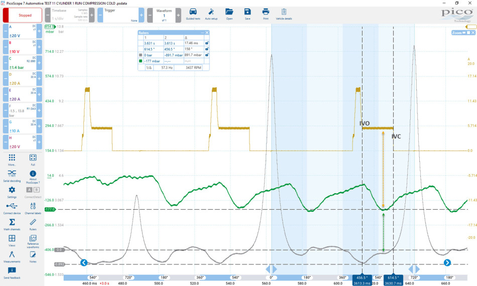
Looking at the waveforms above, it does amaze me how Fiat has been able to infinitely manipulate the four-stroke cycle to achieve superior economy and emissions across the entire engine speed and load range.
Let’s look closer at the IVO event: Traditionally, this valve is opened around 355° ATDC compression to promote internal scavenging and EGR (temperature permitting), however, the IVO event on the Fiat occurred at 456° ATDC compression (midway through the intake stroke 360°-540°) and closes at 614° ATDC compression which is 74° into the following compression stroke. This reduces the pumping losses while still achieving a peak pressure of 12.6 bar in just 106° of crankshaft rotation.
So, based on all the measurements above, had we done enough to prove that our intake valve was not fully opening under certain operating conditions? I think we had established the cause of the misfire but not why. We knew that the inlet valve actuator consumed current when the fault occurred, so we had to assume the ‘work done’ status via the actuator and the PCM/driver. The question, therefore, is what else could cause the inlet valve not to open when commanded by the PCM?
- Mechanical sticking of the inlet valve: To be confirmed with intrusion into the engine
- Incorrect engine oil pressure: To be measured.
- Incorrect engine oil viscosity: Recent oil change confirmed the correct viscosity
- Engine oil contamination/restriction: Recent oil filter change and inspection of inlet valve actuator ’in-line filter’ confirm no contamination
Given this summary of possible causes, and our customer’s comment surrounding a low oil level warning (which may have been an oil pressure warning), the only logical step was to measure the oil pressure with the WPS500X using our Sykes Pickavant adapters. Once we knew that our oil pressure was correct, we would be left with a faulty inlet valve actuator assembly or a sticking inlet valve.
Results
The screenshot below shows the oil pressure values during an initial cold start followed by a static warm-up cycle from 13°C to 63°C (cylinder head temperature). Note the instantaneous rise of the oil pressure in response to WOT applications.
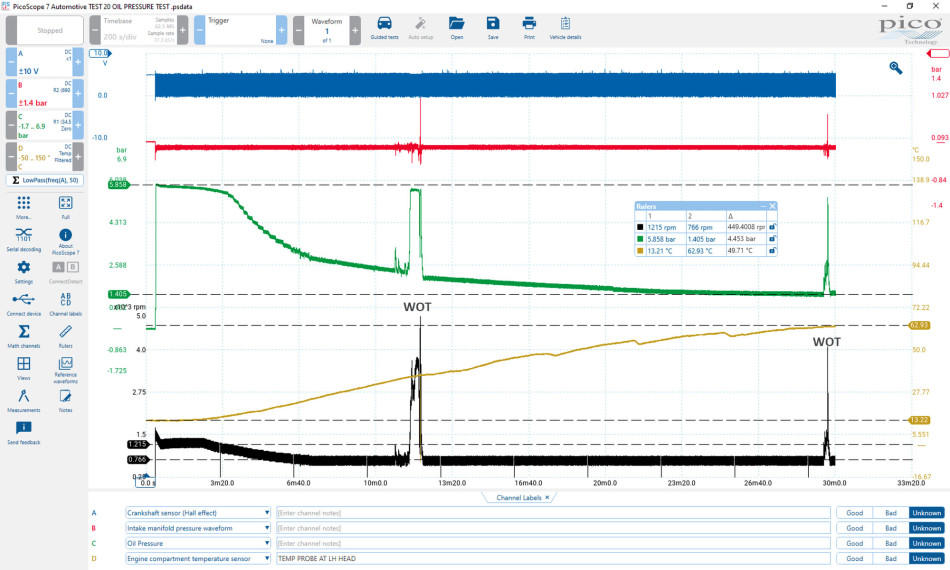
The values obtained above and the rapid rise time all serve to qualify the oil pressure without load. But what about during prolonged road-testing?
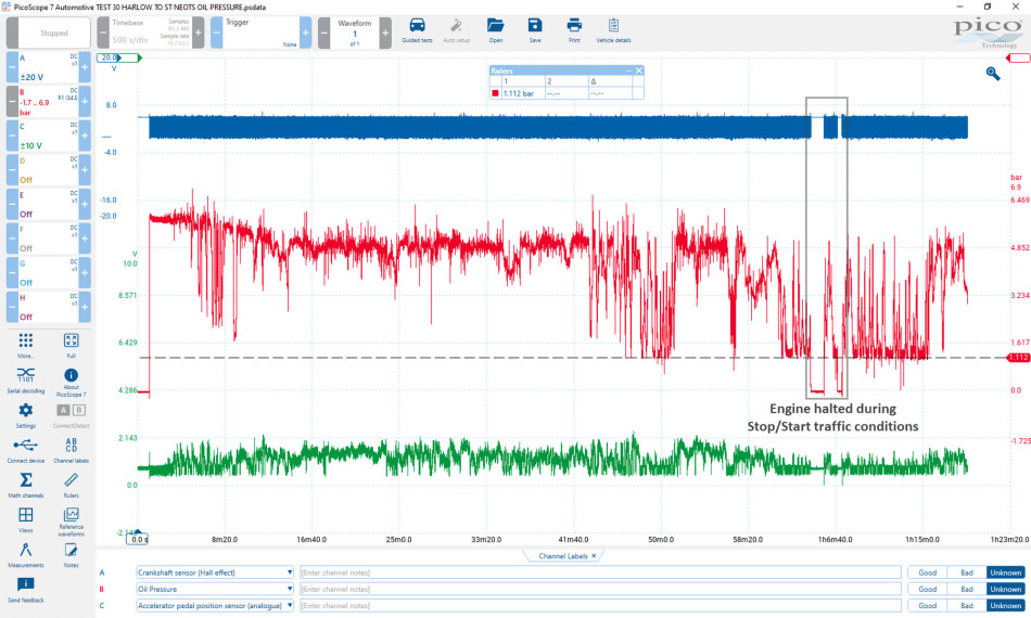
The screenshot below shows the measured oil pressure from Harlow, Essex to Pico UK in St Neots. This journey had numerous load conditions, from high-speed motorway driving to stop/start traffic and everything in-between. The lowest recorded oil pressure was 1.112 bar other than during engine halt conditions in traffic. This data was enough to convince me we did not have an oil pressure issue as alluded to by the customer.
To summarise:
- Our inlet valve for cylinder one failed to open fully, intermittently.
- The PCM control of the inlet valve actuator was correct and the current flow evident when the fault occurred
- The engine oil quality and pressure was confirmed as correct
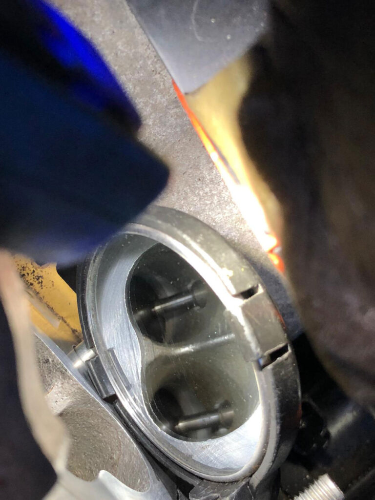
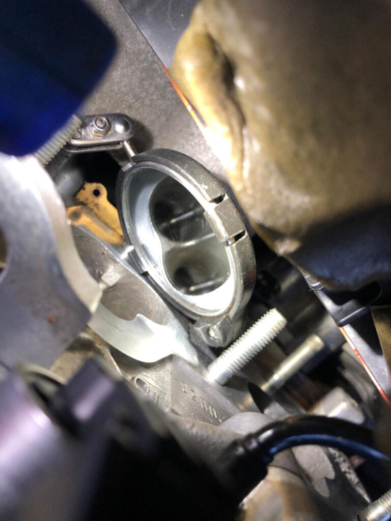
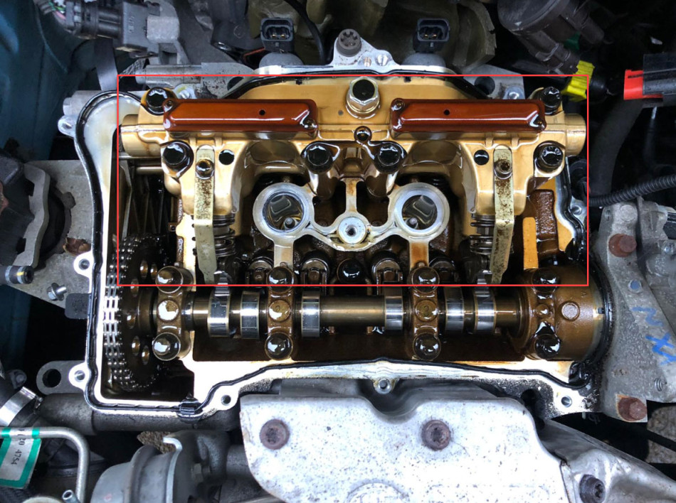
We removed the inlet valve actuator (TwinAir actuator) and inspected the inlet valves for ‘mechanical’ sticking/operation. As you can see below, there were no carbon deposits on the valves or any debris that could intrude between the valve stem and the valve guide.
Physically pressing the inlet valves down (to open) confirmed adequate, smooth closure with no interference or restriction of movement. Further examination of the cylinder head and valve train qualified adequate oil bathing and no damage to the valve springs.
We replaced the inlet valve actuator (TwinAir actuator) and reassembled the engine ready for post-fix measurements at cold start.
Confirmation of repair
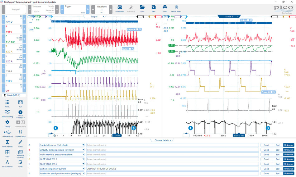
You can see the results of the initial cold start after replacing the TwinAir actuator in the screenshot above. After the initial start-up, we could see stability return to the intake manifold pressure waveform where we had even intake pulsations.
I wanted to focus on the engine speed signal at 2705ms, as I noticed during the initial start-up the engine momentarily misfired. This is one of those heart in mouth moments when you think ‘Have I misdiagnosed?’.
Closer analysis of the intake manifold pressure waveform confirmed that the intake pull during the momentary misfire was stable and equal to the neighboring pulsations. The most likely explanation here is the purging of the fuel lines post start-up or indeed a one-off combustion anomaly as the engine ‘settles’ post-repair.
The beauty of the postfix analysis is that you not only qualify the repair but put your mind at ease when such momentary events occur. (This momentary event was not due to low compression).
The following test captured free-revving of the engine shortly after start-up as misfires may well be more pronounced when cold and under load.
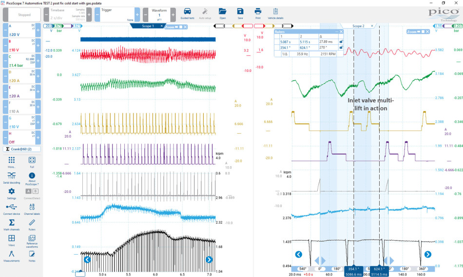
The engine performed flawlessly, but also threw another curveball at me that I had not seen before!
The scope view on the right highlighted a managed inlet valve condition called ‘multi-lift’ at low load, which allows for optimization of combustion in these driving conditions. Note how the inlet valve initially opens around the more conventional crank angle of 354° ATDC compression but closes midway through the inlet stroke (360°-540°) only to open a second time at approximately 540° ATDC compression. How cool is that? You should also note the effect this had on the intake manifold pulsations.
List of parts fitted
- Twin air actuator (Inlet valve actuator assembly).
Conclusion
Reading through this case study, the combination of customer concerns and fault code descriptions had me thinking of all kinds of doom and gloom for this vehicle.
- The customer had mentioned an oil pressure/level warning of some description, but this was never confirmed.
- Lack of maintenance (lubrication service) also raised an eyebrow given the nature of the fault (electro-hydraulic valve train).
- The fault codes alluded to cylinder one temperature too high, which when you put these three symptoms together, you would be forgiven for assuming the worst for this engine (no evidence of overheating was ever discovered).
When taking all the above into consideration, sequenced diagnosis of each customer/fault code description allows you to eliminate fact from fiction and present the repaired vehicle with complete and total confidence.

