A Volvo XC90 with a permanent misfire problem provided an opportunity for a non-intrusive engine condition evaluation. How we tackle such symptoms of misfire is predominately governed by experience, probability and accessibility.
By doing a non-intrusive engine evaluation, you can provide a cost-effective initial diagnosis and deliver conclusive evidence on how to proceed with rectification (if rectification is a cost-effective solution).
A quick vehicle scan revealed a misfire present at cylinder 5 and I had no doubt that further analysis of serial data could well reveal more about the fuelling conditions of that cylinder. Given that a misfire had been detected by the PCM, we were conscious of a fuel injector ‘cut’ shortly after startup (catalyst protection).
Here, then, we had a small window of opportunity to validate the misfire by using emission-related data either via a scan tool or a gas analyser.
Let’s take a step back from serial data. A relative compression test with PicoDiagnostics (PD) will provide a brief evaluation of the fundamental condition of the engine before we get into more intensive diagnostics.
But why would we want to do a relative compression test? Well, why not?
Based on the vehicle’s mileage and the installed gas conversion, valve seating would always be a concern and one we could not afford to overlook. If the relative compression test results were okay, we were justified in performing more intensive diagnostics.
I would rather take this route than carry out intensive diagnostics to find that we have a compression issue. Before we performed the relative compression test, we did a battery test with PicoDiagnostics to make sure that our vehicle’s battery could perform as required:
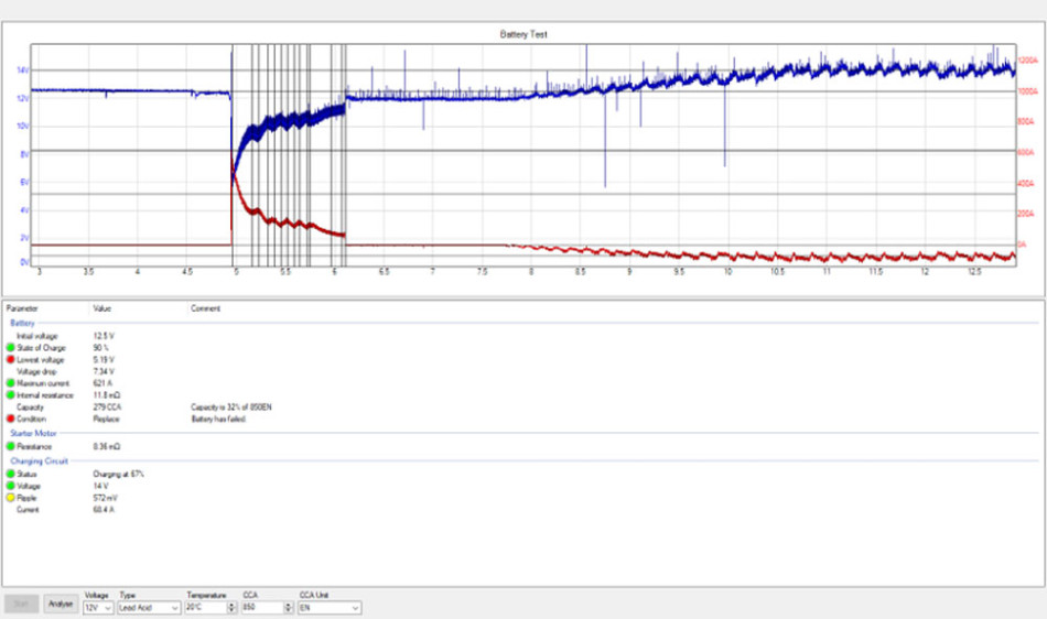
Unfortunately, as you can see above, the 12V battery failed the battery test and would require support for us to continue the testing. While this result was not relevant to the customer’s complaint, the vehicle needed a new battery (at over £100) and we needed to keep this in mind when concluding our diagnosis.
Relative compression test
For this test, we use a x1 test lead connected across the 12V vehicle battery. The results below speak for themselves and we were immediately onto something.
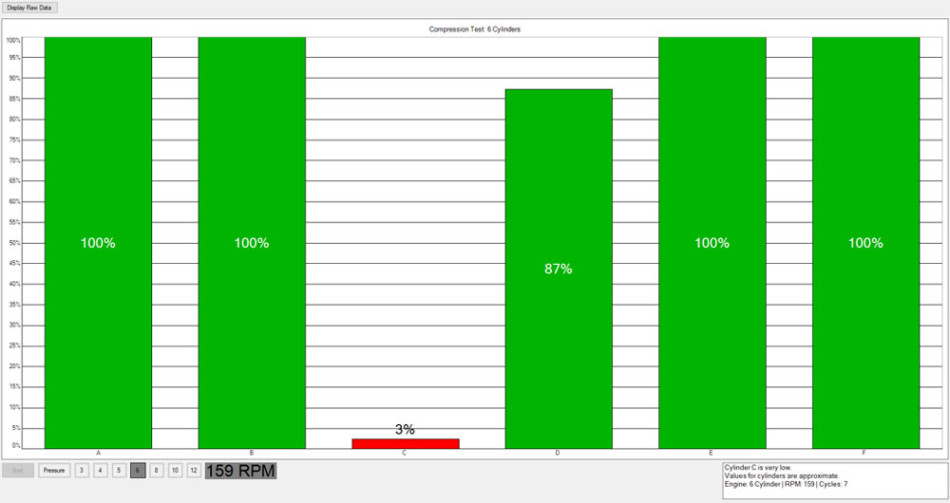
Where is our offending cylinder?
Our scan tool suggested a ‘cylinder 5 misfire’, but how could we be sure? This was the time to switch to PicoScope Automotive and repeat the relative compression test.
For this test, we also incorporated a synchronisation signal from cylinder 1. The image below shows how I have used the PCM trigger signal to the COP at cylinder 1. I could also have used a COP probe for even less intrusion. Based on the firing order 153624, it does indeed look like cylinder 5 is our offender.
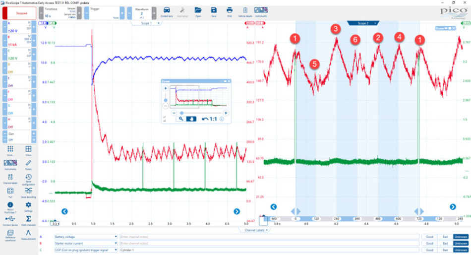
At this stage of the diagnosis, we could conclude that cylinder 5 was misfiring due to a compression issue. We backed this up with evidence from PicoScope, PicoDiagnostics and scan tool data. This was also the time to inform our customer that they needed a new 12V battery.
By using the techniques described above, the biggest intrusion into the vehicle systems proved to be obtaining the PCM trigger signal to COP #1. However, all in all, there was minimal intrusion and we could provide an initial diagnosis. The customer could now make an informed decision on how to proceed. We got permission for further diagnostics to assess the cause of the low compression.
Below we applied a first-look sensor to the exhaust tailpipe and a COP probe resting on the cylinder 1 COP unit. Then we cranked the engine, with the fuel injection prohibited, which aided the analysis of exhaust gas pulsations due to the removal of combustion dynamics in the exhaust system.
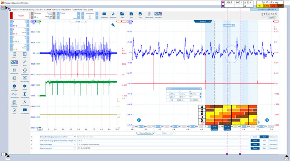
In the screenshot above, you can see that we made use of the cylinder ID chart, provided in the Microsoft Pressure Waveform Overlays software, which qualified a sequential irregularity in the exhaust gas pulsations from cylinder 5.
You could argue that this is expected from a misfiring cylinder and not a worthy test. It did, however, reveal that a considerable negative pressure existed on top of the piston when the exhaust valve opened for cylinder 5. This was denoted by the enlarged negative pulse [below 0 V] highlighted in the blue circle. We will use this information later during our summary.
In the screenshot below we added intake pulsations to the above test by using a WPS500X pressure transducer attached to the inlet manifold. Here the engine is running so that we could evaluate the effects of our misfire on the manifold pressure due to combustion at idle speed.
The fluctuations and overall sinusoidal appearance of the manifold pressure (channel D) became immediately apparent. Note how the intake pull for cylinder 5 was reduced compared to cylinder 1 (highlighted in the blue circle placed around channel D).
You should also note the complexity of the exhaust gas pulsations now that combustion is taking place. With that said, we could still detect a missing pulsation (again highlighted by the blue circle placed around channel A), where uniformity was disrupted during the exhaust event for cylinder 5.
Let’s summarise before intruding further:
- The exhaust gas pulsations (during cranking) confirmed the pressure above the piston for cylinder 5 was lower than the other cylinders.
- The exhaust gas pulsations remained disrupted during idle speed.
- The intake pull for cylinder 5 was reduced compared to the other cylinders.
At this stage, we had remained non-intrusive, but now it was time to remove the spark plugs.
Note: Other than engine covers and hoses, this was the first time that we removed components to perform our diagnostics tests.
In the screenshot below we compared cylinder 2 (blue) to cylinder 5 (magenta) at idle speed.
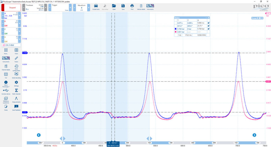
It came as no surprise that cylinder 5 had a lower compression than cylinder 2, but could we see other clues in the above waveform as to why?
Note the deeper expansion pocket of cylinder 5 compared to cylinder 2. Even though our peak compression was low, the swept volume between pistons remained the same. If we start with a low compression at Top Dead Centre (TDC) and our pistons ‘sweep’ identical volumes, then our expansion pocket will inevitably be deeper (lower negative pressure).
Remember that when the exhaust valve for cylinder 5 opened, there was a greater negative pressure above the piston than on the remaining cylinders (see images above).
Let us move on to the 360° point in our four-stroke cycle. Note the delayed ‘defined’ closure of the exhaust valve. Confirmation of EVC was defined by the point at which we achieved peak negative pressure after 360°.
Could this be a retarded exhaust valve event or a poorly seated exhaust valve?
Below we reveal another giveaway in the form of leaning compression towers. This would suggest a leaking cylinder. You can find more information on compression tower symmetry here.
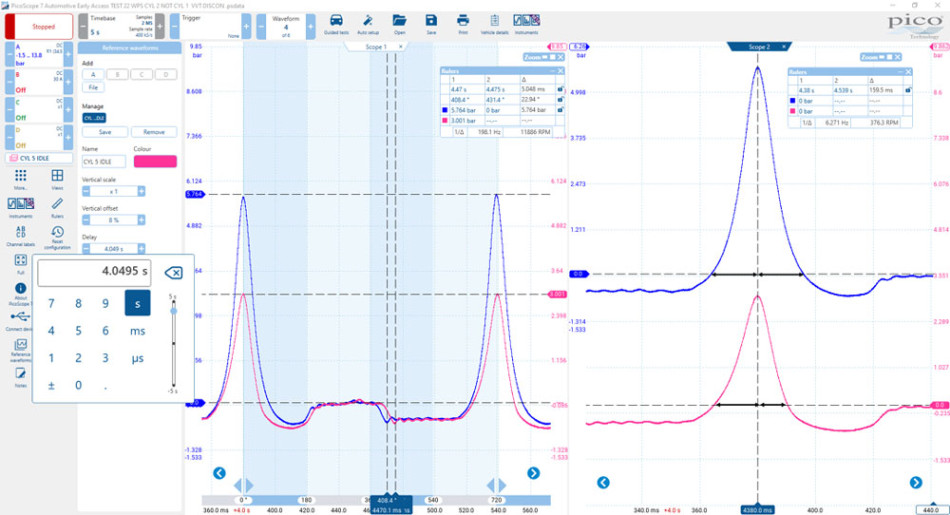
With all things being equal (which they rarely are), the rise and fall in the cylinder pressure during the compression and expansion strokes should be near equal and result in a symmetrical compression tower.
In the image below we look at the valve duration.
Defining the EVC event is always challenging at 360°, but they differ considerably between cylinders 2 and 5, by 27° of crankshaft rotation.
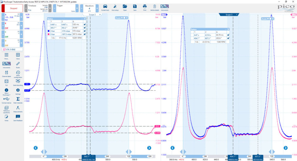
Note the effective intake stroke of 202 .6° measured from peak negative pressure to our inlet valve close event (IVC). Now compare this value to the effective intake stroke of cylinder 5 below at 190.1°.
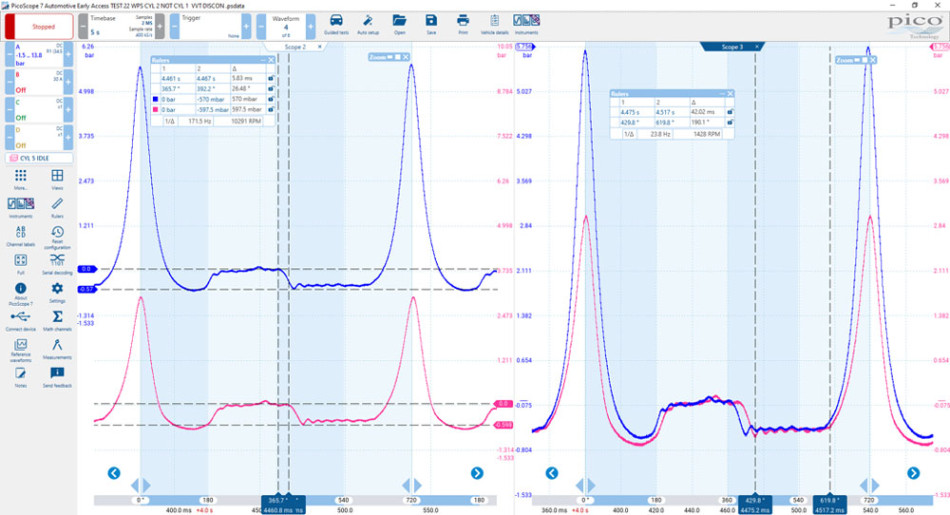
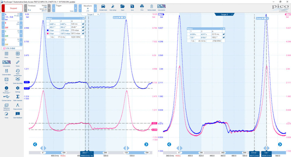
The effective intake stroke would, of course, have a proportional effect on the effective compression stroke. Below you can see an effective compression stroke of 114° for cylinder 5.
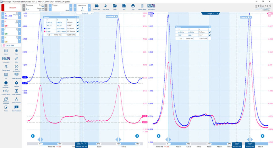
Below you can see an effective compression stroke of 100.2° for cylinder 5.
To summarise:
- Low cylinder 5 compression (peak)
- Cylinder 5 leakage (leaning compression tower)
- Poorly defined EVO
- Poorly defined EVC
- Delayed/poor sealing of EV during the intake stroke
- Reduced effective intake stroke length (cylinder 5 reduced by approximately 12° of crankshaft rotation)
- Reduced effective compression stroke length (cylinder 5 reduced by approximately 14° of crankshaft rotation)
Conclusion
We have a number of issues with cylinder 5 and of course this engine in general. The above summary provides detailed information for our customer and the technician who will be tasked with the repair.
Such detailed information helps to focus our attention on specific areas of the valve train during rectification which may have been missed if not documented. I am thinking here particularly about the delayed EVO/EVC event which may reveal issues around hydraulic lifters/followers and the integrity of the engine oil pressure/passages.
Reading this back I should have added that crankcase pressure is another non-intrusive pressure test you can carry out. The vehicle has now moved onto pastures new where feedback is highly unlikely unless, by some freak of nature, it is returned to the same workshop by a different owner for diagnosis.
Thanks to Kevin Ives at Ives Garage for his support throughout this diagnosis.
Click here for more Pico Technology case studies.


