Pico Automotive shares a recent example of how a technician solved a customer’s complaint on their 2010 Tesla Roadster.
Job sheet
- Vehicle: Tesla Roadster 2.0
- Year: 2010
- Mileage: 70,000
- Transmission: Single speed fixed gear
- Fuel: Electric
- Customer complaint: Illuminated ABS and traction control warning lights. Loss of traction control, loss of regenerative braking, reduced vehicle driving range
At normal road speeds, the ABS and traction control warning lights were illuminated.
The symptoms were present at every drive, regardless of temperature and road conditions, and had been present for over a week.
The warning lights were lit as long as the ignition was on.
The customer interview confirmed a full service history with no accessories installed but that the front ABS sensor on the left-hand side had been replaced recently.
ABS sensor recently changed
We verified the customer complaint and confirmed the vehicle’s ID, specification, and that there were no relevant outstanding known issues.
The visible ABS connections were secure and the wheel/tire combination had the correct specifications for the vehicle.
We also checked tire wear, brand, orientation, condition and pressure and found it all to be in order.
We discovered that the wheel speed sensors fitted to the vehicle fall under the active design type, which can present a challenge to technicians as the output can vary from 5 to 15 mA.
We set the vehicle to engine on, in neutral, and raised off the ground with the wheels free.
When rotating each wheel, the traction control light flashed on the instrument panel.
We can only assume that this is the detection of wheel slip, or some form of confirmation feedback, to enable rapid location of offending wheel speed sensors.
The right-hand rear wheel alone did not cause the traction control warning light to flash.
Our initial test was to confirm power, ground and signal from the ABS sensor.
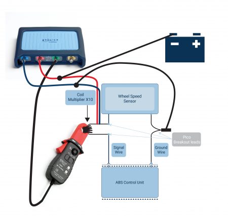 We used Pico’s 30 A current clamp with a current multiplier and the relevant Pico breakout leads, we could measure the expected low-switching current.
We enabled the hardware filter in PicoScope six to remove noise from the signal and improve the resolution of the switching current at the wheel speed sensor.
With the ABS sensor circuit interrupted, we also seized the opportunity to monitor the sensor ground return line and the power supply (AC and DC coupled).
We originally used the AC coupled measurement to provide improved vertical resolution of the DC voltage ripple (speed signal), but further analysis post-capture provided additional information.
Tech tip: The connection to the sensor (Channel A) is for the 4225 and 4425 models of PicoScope as they allow the ground level to float ± 30 V from the battery ground. This connection method is fine for inspection of the ABS sensor power and ground (using a single channel) when the wheel is spun by hand (low frequency only).
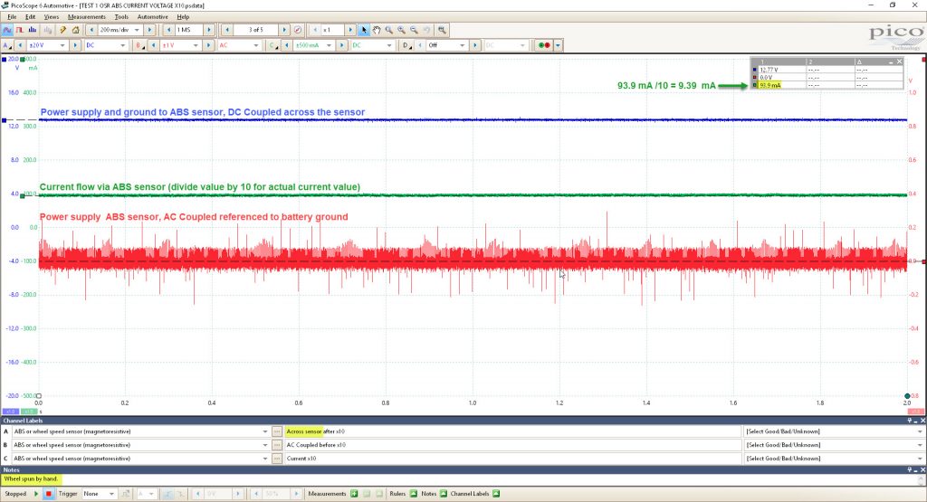
Initial PicoScope waveform.
The waveform confirms that not only is there no output when the wheel is spun by hand but also that the power supply and ground to the ABS sensor are present on channel A, referenced to sensor ground.
The ABS controller permits power supply to the sensor, which suggests that the circuit is intact.
The noise present on the signal wire suggests that the circuit to the battery and vehicle ground on channel B is intact.
The current flow is present via the sensor (9 mA) regardless of wheel rotation.
There is no speed signal generation during wheel rotation.
We can, with a degree of confidence, accept the integrity of the wheel speed sensor circuit to be normal.
If the ABS control unit detected a short to ground (through excessive current flow), the scope would have detected a momentary 12 V supply (at ignition on) with a rush of current followed by 0 V as the control unit shut down to protect the system.
The minimal current flow via the sensor (9 mA) with power and ground present on channel A suggests there is no short to ground.
A short to ground would minimize the characteristic noise captured on channel B (AC coupled).
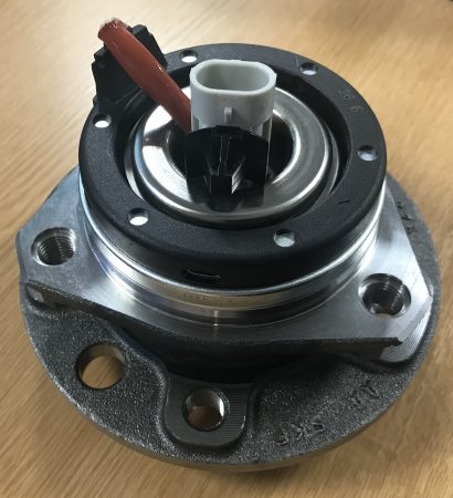 The grey area here is the condition of the ABS pickup ring, as access is near impossible without removing the ABS sensor, an integral part of the hub assembly.
However, the purchase of a new hub included the ABS sensor and pickup ring and so there was no need to dig further.
With the new hub assembly installed, the new waveform below confirmed the repair.
The math channel (black) divides the values of channel C by ten to determine the correct current value flowing through the ABS wheel speed sensor.
With no Tesla scan tool available to erase the ABS fault code, we had to do a number of road-tests before the system would accept that the wheel speed signal was back online.
Once this state had been confirmed, all warning lights extinguished and traction control and regenerative braking were restored.
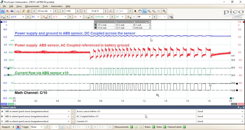
Final PicoScope waveform confirms repair.
For further information about PicoScope and for more case study repairs, click ‘more details’ below.


