Nick Hibberd of Hibtech Auto-Electrical Diagnostics continues his tips and advice for PicoScope users with part-two – catch up with part one here.
The fact that there is a part two to this article should have suggested that cleaning up the LH rear wheel speed signal didn’t solve the problem.
During the first few yards of driving after the repair, the ABS kicked in again when approaching a stop. There was another problem somewhere.
I sat in the car and thought about the fault found and the repair.
Everything pointed to a wheel speed sensor (WSS) problem, and one had been found, so it was back to the beginning.
Not mentioned in part one was how and where the signals were picked up.
I like to go directly to the ECU pins so that I see through the scope exactly what the ECU sees.
For different reasons in this particular instance, I elected to go straight to the WSS themselves.
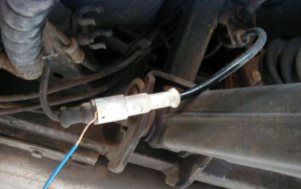
It proved a little awkward because there was no chance of back probing the pins on the WSS connectors, but I found a way: I looped cable strands around the speed signal male pin that were just thin enough to enable it to fit back together without damage.
Capture one was taken at about 10 mph.
This is another good reason to correlate WSS signals on the same axle, as the frequencies of the signals should be near identical.
Look carefully for differences between the signals.
It is common for a system to have a different number of rotor teeth on the front and rear axles, but there is never a difference between the LH and RH sides.
I’ve even witnessed tyres of the same size but from different tyre manufacturers on the same axle resulting in different wheel speeds.
I always recommend to the vehicle owner to fit the same manufacturer’s tyres — preferably all round, but definitely on the same axle.
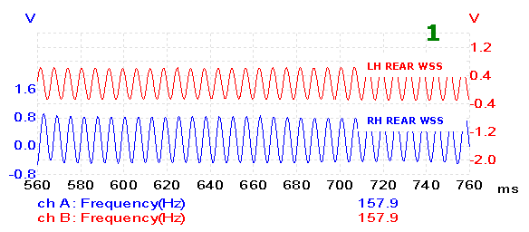
Here the signals and frequencies matched.
If we really scrutinise the capture we can see a slight peak-to-peak difference between the two, but this shouldn’t matter too much as there is always a slight discrepancy between sensors.
So now what?
I wasn’t about to give in on the possibility of a WSS signal problem causing this vehicle fault, and at my last count cars had four wheels.
I decided to check the front axle WSSs.
In this case, I knew that the frequencies could differ between the two axles, so I was more interested in the signal amplitudes.
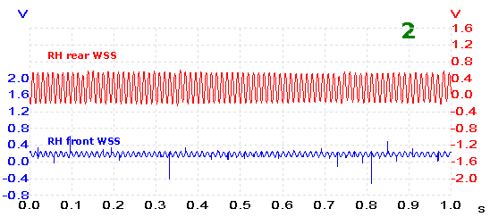
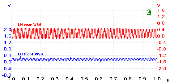
Captures two and three were taken at about 10 mph, and this time they show the WSSs on the same side.
Immediately there’s a problem: the front signals have badly lost amplitude. Don’t pay too much attention to the sudden bursts in EMF in capture two, as this was due to interference entering my make-shift test cables scattered round the car.
Something struck me as odd: both front signal amplitudes were reduced by the same amount.
One reduced sensor signal would definitely indicate a fault, but with both WSSs on the same axle showing almost identical signal shapes, I briefly considered this as being normal.
At this point I began to doubt my measurements. I took several captures of these signals, making sure the connections were good, the correct sensor cable was being monitored (remembering that one of the cables is indirectly connected to ground), the scope grid was set up correctly, swapping the channels over in case I had a leak to ground, and anything that could possibly explain both sensors reading the same low amplitude.
I eventually concluded that this couldn’t be normal for the exact same reason I condemned the LH rear sensor signal in part one.
In this case, when approaching a stop, the front sensor signals became become too weak for the ECU to correctly register the vehicle speed; and because the rear sensors were still producing a good signal, the ECU would have assumed that the front wheels had locked up and so activate the ABS.
Normal or not, the findings do relate to the initial game plan of a sensor signal problem.
I set out to find a common factor linking both WSSs which would cause the low-amplitude signal.
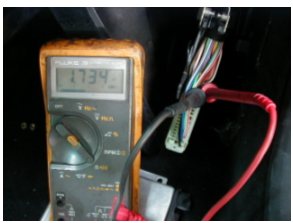
I extensively investigated both front WSS circuits for possible leakage to battery negative, battery positive, each other, all other cables within the ECU block, ignition on and off, high resistance within sensor cabling, ECU connected and disconnected, and everything else I could think of.
In short, I was struggling to find anything electrically wrong, and there was certainly nothing to suggest that these sensor circuits had something in common, other than the normal sensor grounding path through the ECU.
This also checked out OK.
So if not electrically, what about mechanically?
To investigate a mechanical reason for the poor signal amplitudes, we now need to focus on the wheel hub at each corner of the car, which means we are no longer looking for a common link but more of a coincidence that just happens to affect both sensors to an equal degree.
As an Electrical Tech I’ve been caught out more than once when dealing with coincidences, but in this case I didn’t have much else to go on.
I approached each problem WSS individually and for the moment ignored the fact that two WSSs had been affected.
What was I looking for?
Nothing has changed from the operating factors explained in Part one.
In order to create a valid wheel speed signal from a variable reluctance sensor, we need only a few key factors:
- Sensor internal magnetic strength
- Number of windings within the sensor
- General shape and composition of moving reluctor
- Distance between sensor and moving reluctor
- Speed at which the moving reluctor passes through the sensor’s magnetic field
Sensor internal magnetic strength
We can’t rule this one out.
If the magnet held within the sensor’s core has deteriorated or degraded, the passing inductor (toothed rotor) won’t distort the magnet’s flux to the same degree and so we end with a weak generated EMF — the fault.
I’ve had past instances where the sensor magnet has been reduced to almost powder form.
Number of windings within the sensor
This is very unlikely.
The number of windings makes up nearly all of the sensor’s resistance and this has already been verified at 1.734 kΩ.
It is, however, possible for the windings to short together internally, but this would result in a reading lower than 1.734 kΩ depending on where the short was inside the sensor windings.
The fact that we have a good sensor resistance reading means it’s safe for the moment to exclude this.
General shape and composition of moving reluctor
This again is very unlikely.
Firstly, if the composition of the reluctor were affected, each tooth would have to change by the same amount, which seems highly improbable.
Secondly, if the shape of the teeth was wrong, every one would have had to be affected in exactly the same way.
The captured signal showed no missing or bad teeth, only a low amplitude.
Distance between sensor and moving reluctor
This is the favourite, based on my experience and for practical reasons.
A distance error between the sensor and the reluctor would leave the sensor resistance alone and the general shape of the signal intact.
It’s not unusual for corrosion to build up between the base of the sensor and its face-to-face contact with its mounting, even though the two contact faces are held together with a securing bolt.
The sensor rotor gap need only be altered a fraction to make a very noticeable difference.
Speed at which the moving reluctor passes through the sensor’s magnetic field
This has to be the least likely of all. If the rotor speed was an issue, it would rightly affect the amplitude of the signal, but the frequency would suffer too. If you look closely at either capture two or three you will see that the frequency of our weak signal is almost identical to the known good rear traces, so we can conclude that the rotor is in fact rotating at the same speed.
When we break the sensor’s operation down and eliminate some of the factors involved, we’re closing in on what is the problem.
It’s looking like a sensor-rotor gap problem.
As long as I stick to the sensor’s basic operating rules then it should be easy.
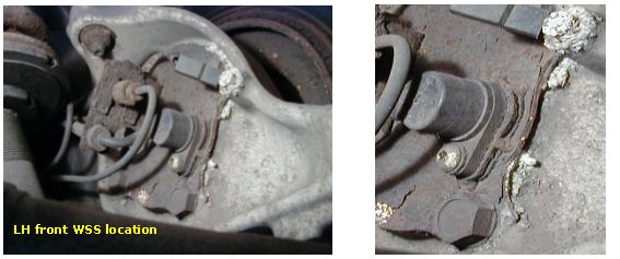
This shows the typical location of a front WSS.
It mounts onto a cover plate and this plate is bolted to the rear of the hub.
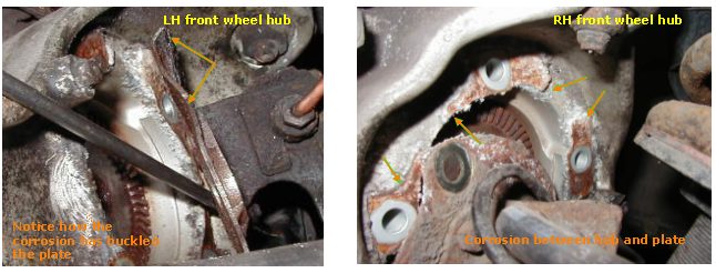
Firstly we can see a white fuzzy build-up around the back plate fixing bolts, and this corrosion seems to have settled in a gap between the plate and the hub face.
Was it normal? Was the gap deliberate?
A quick visual inspection around the hub didn’t show much else wrong.
Ordinarily I would remove the sensor and start collecting measurements to get an idea of the gap between sensor tip and rotor teeth, but with this sensor’s mounting plate being easy to remove I could now see what exactly was going on behind the sensor.
With the back plate removed, the root problem became clear.
